Analysis model: gpt-5.5 xhigh
Verses by Electromotive Force - Technical Dissection
Scope
This is a static binary dissection of Verses by Electromotive Force, released
for MS-DOS at Assembly 1994. Demozoo and Pouet both list it as the 1st-place
entry in the Assembly 1994 PC demo competition. In the current repo sequence,
this starts filling the Assembly 1994 top-three PC demo set.
Useful public references:
- Demozoo production: https://demozoo.org/productions/6785/
- Demozoo competition: https://demozoo.org/competitions/676/
- Pouet production: https://www.pouet.net/prod.php?which=67
- Pouet Assembly 1994 results: https://www.pouet.net/party_results.php?when=1994&which=7
- Scene.org archive: https://files.scene.org/get/parties/1994/assembly94/demo/emf_vrs.zip
- Pouet-linked AVI reference: https://ftp.untergrund.net/users/rarefluid/67_EMF_-_Verses.avi
The analysis is based on the released archive, the NFO, UNP-unpacked executable
code, the appended resource table, 16/32-bit x86 disassembly, and a public
video-reference capture for effect timing. Offsets such as 0x304a6 refer to
offsets in the UNP-expanded MZ load image after stripping the executable
header. Offsets explicitly named as overlay+... refer to the appended data
area after the MZ image. Resource-table offsets are absolute offsets in
VERSES.EXE, not overlay-relative offsets.
Examined Files
The archive contains four files:
FILE_ID.DIZ       BBS file description
VERSES.EXE        single executable containing PMODE code and appended data
EMF.NFO           group info
VERSES.NFO        production info, requirements, credits, technical notes
Hashes from the examined files:
42312e5aba5e09471c18c1f347118d40b4e6ec13abd301bb08cbd3af8030f657  emf_vrs.zip
f3784702213a7a40ff8788bd5ac3f550f8050a369cc7a6b2615e2fc957960460  FILE_ID.DIZ
7073c9bb3303bf08e0e387beb7ba07d9e88043ad15300da51d32744de3343a84  VERSES.EXE packed
6726fdc86fd2072b76189a2c1e8426f793317ed47c96158ceee4f20ea6290360  VERSES.EXE after UNP
3268eb6a910830146f59e4fe21bba3e7f1b0e8d1365f3806d024489dbbe0d79e  EMF.NFO
cd6b26396f1cc3de66c78982e5f48e628be3a7af150ebadb534f59f6fd00780d  VERSES.NFO
68d3dd0344184513b0e7bc1cf41107464576f39d6a4bf36990474f9f515f2b5c  67_EMF_-_Verses.avi
The AVI reference is 512x384 MPEG-4 video at 25 fps, duration about 266.08 seconds. The screenshots below use that public capture's timestamps; they are not local DOSBox-X timestamps.
The NFO states that the demo uses a slightly customized PMODE 2.24 by Tran, is coded in assembly, is optimized for i486, needs a 386sx or better, VGA, about 400 KB conventional memory, at least 1 MB extended memory, and a Gravis Ultrasound for music. It explicitly does not include Sound Blaster music support.
Credits relevant to the code/effects:
Saracen          voxel cave, bitmap rotation, ripple, dotfade, kaleidoscope,
                 julia morpher, greetings, credits/frontend routines
The Grim Reaper gouraud routines, design star, IFS morpher, diagonal dotfade,
                 Bill Gates whirl, EMF gouraud logo
Devastator       mosaic, polygon ball, file routines, music routines/frontend
Saint            presentation text, Bill Gates writer/mutation, music routines
Whalebone        music and some graphics
I am intentionally not reproducing old phone/address/BBS contact data from the NFO.
Executable Shape
The original VERSES.EXE is not just a flat DOS MZ program. The packed file has
a small initialized MZ image and a large appended data area:
Packed file size:      1,030,549 bytes
Packed MZ size:            86,951 bytes
Packed load image:         86,919 bytes
Packed overlay/data:      943,598 bytes
Header size:                  32 bytes
Relocations:                   1
Entry CS:IP:           FFF0:0100
UNP expands only the MZ image. The appended data stays byte-identical and at the same length:
UNP file size:         1,315,177 bytes
UNP MZ size:             371,579 bytes
UNP load image:          371,467 bytes
UNP overlay/data:        943,598 bytes
Header size:                 112 bytes
Relocations:                  20
Entry CS:IP:            0000:03C1
Initial SS:SP:          5AB1:1C00
This matters. The front of the original file is a real-mode unpacker. After UNP, the visible image contains:
0x00000..0x01bxx  PMODE/VCPI/DPMI/bootstrap strings and transition code
0x01c1c..0x01d09  VGA helper routines: vertical retrace, DAC, mode/tweak setup
0x01d1a..0x01e1x  timer IRQ and keyboard IRQ handlers
0x04a00..0x04e40  file/overlay table loader and simple resource depacker
0x05223..0x05cxx  frontend, sound-system dispatch, GUS driver setup
0x2005d..0x20671  affine/texture/palette-controlled effect loop cluster
0x211b8..0x2161f  text/presentation renderer and screen reveal loops
0x2273c..0x22fxx  heavily unrolled span/warping table builder
0x30000..0x304e9  3D transform, projection, face culling, polygon span filler
0x59c70..0x5a390  planar VGA blit/twister/palette routines
The higher chunks are reached through part-specific dispatch tables and loaded
resources rather than through a neat main()-style sequence. The demo is a
single executable with internal part scripts and an embedded file system.
Appended Resource Table
The appended overlay ends with an EMF! signature and a compact directory.
The first record starts at file offset 0xfb6a9, which is overlay+0xe6302
relative to the packed MZ image. The EMF! signature follows at file offset
0xfb991. Entries are laid out as 32-byte records:
name[16] file_offset stored_size packed_flag unpacked_size
Examples from the table:
tausta.dat     file 0x000153a7  stored 0x009e92  packed 1  target 0x012c00
anprod.sci     file 0x0001f239  stored 0x000bc8  packed 1  target 0x00fd0a
xwarp.sci      file 0x0001fe01  stored 0x007407  packed 1  target 0x00fd0a
xwarp.scr      file 0x00027208  stored 0x00339b  packed 1  target 0x00918c
doors.pic      file 0x0002b72e  stored 0x0018d5  packed 1  target 0x00fd00
doors.snd      file 0x0002d003  stored 0x01833a  packed 1  target 0x02b90d
cave.dat       file 0x0004533d  stored 0x00589e  packed 1  target 0x010000
ripple.pic     file 0x0004abdb  stored 0x005bff  packed 1  target 0x00fa00
imagine.sci    file 0x000507da  stored 0x002584  packed 1  target 0x00fd0a
endlogo.pic    file 0x00052d5e  stored 0x002f4b  packed 1  target 0x00fd00
ss.dat         file 0x00055ca9  stored 0x01393b  packed 1  target 0x01f400
vscroll.pic    file 0x000695e4  stored 0x000cb5  packed 1  target 0x001680
credits.dat    file 0x0006a299  stored 0x001a9c  packed 1  target 0x005e68
dt.mod         file 0x0006bd35  stored 0x03ac12  packed 0  target 0x03ac12
titlepic.pic   file 0x000a6947  stored 0x00fd00  packed 0  target 0x00fd00
ripple.dat     file 0x000b6647  stored 0x00fa00  packed 0  target 0x00fa00
ripple.pal     file 0x000c6047  stored 0x000300  packed 0  target 0x000300
vertlogo.img   file 0x000c6347  stored 0x002bc0  packed 0  target 0x002bc0
imfont.dat     file 0x000c8f07  stored 0x0036a2  packed 0  target 0x0036a2
twist.dat      file 0x000cc5a9  stored 0x00fa00  packed 0  target 0x00fa00
twist.pal      file 0x000dbfa9  stored 0x000300  packed 0  target 0x000300
twist.pic      file 0x000dc2a9  stored 0x01f400  packed 0  target 0x01f400
The directory explains why the executable itself contains so many filenames even
though the archive has no separate part files. The parts ask the internal loader
for resource names, and the loader resolves them inside the appended overlay.
For the packed .sci resources, the table target is the loader's requested
resource target size, not proof that the final on-screen representation is raw
chunky pixels. xwarp.sci, for example, begins with RIX3 40 01 c8 00, so the
loaded stream still has an image-format header before any part-specific image
decode.
Overlay Loader and Depacker
The loader core at 0x4c43 takes a requested filename pointer in EDX, a
destination in EDI, and optional offset/length controls in EBX/ECX.
The lookup path:
0x4c43  save registers, store caller offset control at 0x3346
0x4c4a  if table pointer/count 0x3352 is zero, fall back to DOS file path
0x4c75  copy requested ASCIIZ name to scratch at 0x3332
0x4c87  start scanning table at 0x335e
0x4c92  compare first 12 name bytes as three dwords
0x4caf  advance by 0x20 bytes per table entry
0x4cbb  on match, load file handle/segment state from 0x3b5e into 0xd4
0x4cc7  seek to table offset + requested suboffset
When the table entry has packed_flag == 1, execution goes through the resource
depacker:
0x4ce0  test entry+0x18 for packed flag
0x4ce6  allocate/prepare a temporary buffer for stored_size bytes
0x4d06  read stored_size bytes from overlay into that buffer
0x4d1d  EBP = stored_size, ESI = temp buffer
0x4d29  call depacker at 0x4e09
0x4d34  release temporary buffer
The depacker at 0x4e09 is a small run/literal stream, not a heavyweight
dictionary compressor:
0x4e0d  CL = input_byte & 0x3f
0x4e14  bit 6 says length extends into next byte
0x4e22  count = encoded_count + 1
0x4e25  bit 7 selects run mode
0x4e29  literal mode: rep movsb from packed input to output
0x4e2d  run mode: read one byte, rep stosb to output
0x4e34  loop until bytes consumed reaches stored_size
So the table supports both raw resources (dt.mod, titlepic.pic, twist.pic)
and simple RLE-packed resources (cave.dat, doors.snd, ss.dat, many
screens/scripts).
PMODE and Machine Setup
The unpacked entry at 0x03c1 is the PMODE bootstrap. It is still 16-bit code
using many 32-bit operand/address prefixes.
Important checks and setup:
0x0356  386+ check using FLAGS high bits
0x0377  SMSW protected-mode/V86 check
0x045d  DPMI probe via int 2f, AX=1687h
0x0468  VCPI probe through int 67h path
0x0472  XMS probe via int 2f, AX=4300h
0x048c  A20 fast gate attempt: in/out port 92h, set bit 1
0x04a2  keyboard-controller A20 attempt: out 64h D1h, out 60h DFh
0x04c5  PIT-based fallback/memory stability check using ports 43h/40h
The direct protected-mode entry path:
0x01e7  lgdt [0x0c46]
0x01ec  lidt [0x0c40]
0x01f1  mark TSS descriptor byte at 0x0f09 as 89h
0x01f9  mov eax, cr0
0x01fc  set PE bit
0x01fe  mov cr0, eax
0x0201  far jump to selector 20h, offset 0206h
0x0206  load TR with selector 30h
0x020c  jump to 0x0e7f
The DPMI path is more verbose. Around 0x0702..0x08c7, it allocates selectors,
builds descriptors for the code/data spaces, queries free memory with DPMI
function 0500h, allocates linear memory with 0501h, and fills per-selector
base/limit data. The final far handoff at 0x08dc..0x08eb pushes the prepared
selector and offset and uses a 32-bit far return. The surrounding thunks at
0x0e7f..0x112e bridge interrupts and callbacks between PMODE's real-mode and
protected-mode sides.
The important practical result is that the demo code can address linear memory
directly, including VGA memory at 0xa0000, while still using protected-mode
interrupt callbacks for timer, keyboard, DOS file access, and GUS playback.
Timer and Keyboard Interrupts
The timer handler at 0x1d1a is the central scheduler.
0x1d1a  load demo data selector from CS:[0x1e]
0x1d23  send PIC EOI: out 20h, 20h
0x1d27  if byte [0x0b2e] != 1, skip most scheduling
0x1d34  increment word [0x0ae5], the frame/tick counter waited on by parts
0x1d3b  if callback [0x0b48] is nonzero, call it once and clear it
The CRTC start-address scroll/page path is inside the same IRQ:
0x1d54  if byte [0x0b2f] != 1, skip display-start update
0x1d5d  EBX = [0x0b34] + [0x0b38]
0x1d69  wrap to zero if EBX > [0x0b3c]
0x1d73  if unchanged from [0x0b30], skip hardware write
0x1d7b  store new start at [0x0b34]
0x1d81  DX = 3d4h
0x1d85  AL = 0ch, AH = high byte; out AX,DX
0x1d8b  AL = 0dh, AH = low byte; out AX,DX
Then the handler re-arms the timer:
0x1d91  wait for retrace edge through 0x1c1c
0x1d96  out 43h, 34h
0x1d9c  AX = [0x0b2c]
0x1da2  out 40h, low byte
0x1da6  out 40h, high byte
Two callbacks are serviced after reload:
0x1daa  if [0x0b44] != 0, call it once and clear it
0x1dc4  if [0x0b40] != 0, call it as a persistent per-tick callback
The keyboard IRQ at 0x1dd7 is similarly minimal:
0x1de3  AL = in 60h
0x1de5  ignore break codes where bit 7 is set
0x1de9  save make code to [0x0af0]
0x1dee  pulse port 61h bit 7 to acknowledge keyboard controller
0x1df8  out 20h,20h
0x1dfc  if [0x0af0] == 1, enter the shutdown/exit path
This division is important: most effects do not poll the timer directly. They
install callbacks or wait for 0x0ae5 to advance, and the IRQ calls their
per-frame step.
VGA Register Helpers
The small VGA helpers around 0x1c1c are reused across parts.
Vertical retrace waits:
0x1c1c  DX = 3dah
0x1c20  in al,dx
0x1c22  test bit 3
0x1c24  loop while in vertical retrace

0x1c26  same port
0x1c2a  loop while not in vertical retrace
Black DAC setup:
0x1c30  DX = 3c8h, AL = 0
0x1c36  out DAC index
0x1c37  DX = 3c9h, ECX = 0x300
0x1c40  output zero 768 times
Attribute/overscan helper:
0x1c47  read 3dah to reset attribute flip-flop
0x1c4d  DX = 3c0h
0x1c50  select attribute register 11h
0x1c53  write byte [0x0ae4]
0x1c59  write 20h to re-enable display
Mode/tweak helper:
0x1cc7  DX = 3c4h, AX = 0604h, out AX,DX       ; sequencer memory mode
0x1cd1  read 3dah, then write attr 10h = 61h
0x1ce3  touch CRTC register 07h and force bit 4
0x1cf0  write CRTC 11h
0x1cfa  stream seven dwords through outsl
The higher parts then write directly to 0xa0000 - [0x18], where [0x18] is
the PMODE linear-base correction.
Gravis Ultrasound Path
There is no Sound Blaster path. The GUS code starts by parsing ULTRASND from
the DOS environment.
At 0x565a:
0x565a  EDI = environment segment from PSP via GS:[PSP+2c]
0x5670  ESI = literal at 0x4dfa, the string "ULTRASND="
0x5675  compare bytes while scanning ASCIIZ environment strings
0x569c  parse base port high digit
0x56a2  base = (digit << 4) + 0x200
0x56b4  parse DMA digit
0x56c8  parse IRQ, including two-digit 10..15 form
0x56f9  save parsed IRQ/control value to 0x52f2
GUS reset/voice register setup then uses the base port in [0x52ea].
The code repeatedly writes a register index to base+0x103, then writes data
through base+0x105 or nearby GUS data ports.
The reset sequence at 0x574d:
0x5755  DX = base + 103h, AL = 4ch, out
0x5761  DX += 2, AL = 0, out                 ; reset off/clear
0x576b  dummy reads from base
0x5778  select 4ch again
0x5785  write 1                              ; reset on
0x579b  select 41h, write 0
0x57ac  select 45h, write 0
0x57c3  select 49h, write 0
0x57df  read base+6
0x57ef  select 41h, read
0x5802  select 49h, read
0x5815  select 8fh, read
The voice initialization loop at 0x581c initializes 32 voices:
0x581c  ECX = 0x20
0x5821  decrement voice index
0x5828  out voice select to base+102h
0x5838  write register 00h = 03h
0x5849  write register 0dh = 03h
0x5860  write register 06h = 3fh
0x5877  write register 09h = 0000h
0x588e  loop until all voices configured
Sample upload is at 0x5996. It copies a block descriptor into a local table
and streams bytes through base+0x107:
0x599f  pick descriptor slot = [0x5302] * 0x14 + 0x530a
0x59ad  copy block fields from caller descriptor
0x59d4  EBX = remaining byte count
0x59d8  clamp transfer chunk to ECX
0x59de  call source-supply callback through [0x4df6]
0x59e9  set GUS address low through register 43h
0x5a03  set GUS address high through register 44h
0x5a1f  DX = base + 107h
0x5a25  AL = [ESI], out, increment ESI/EDI
0x5a2a  loop for chunk
0x5a32  align next allocation to 32 bytes
Playback of a loaded sample uses 0x5a56, which selects the voice, computes
the sample start/end addresses in GUS address units (<< 9), and writes
registers 0b/0a/03/02/05/04/00 depending on loop flags. This is a direct GUS
hardware driver, not a high-level library call.
Presentation Text Renderer
The presentation part around 0x211b8 and 0x21310 uses imagine.sci and a
font buffer to draw block text to mode 13h.
Screen initialization:
0x211c3  AX = saved mode word
0x211c9  EDX = 0xa0000, call PMODE video/mapping helper through [0x30]
0x211d4  EDI = 0xa0000 - [0x18]
0x211df  EAX = 0x0f0f0f0f
0x211e4  ECX = 0x3e80 dwords
0x211e9  rep stosd, clear 320*200 bytes to color 0fh
The actual character renderer is 0x21310:
0x21310  EDI = VGA base
0x2131b  EBX = 0x1f7e8, the 16*20 character-state grid
0x21320  outer row count = 0x10
0x21326  inner column count = 0x14
0x2132d  glyph_index = byte [EBX]
0x2132f  glyph_offset = glyph_index * 0xd0
0x21335  ESI = 0x1f928 + glyph_offset
0x2133d  glyph row count = 0x0d
0x21342  ECX = 4 dwords per glyph row
0x21347  rep movsd, copy 16 bytes of glyph pixels
0x21349  EDI += 0x130, advance to next scanline at 320-byte stride
0x21353  after one character, EDI -= 0x1030 to return to top of next cell
0x2135d  after one text row, EDI += 0x0f00
That is a cell renderer for 20 columns by 16 rows. Each glyph is 16 pixels wide
and 13 scanlines high, copied as four dwords per scanline. The state update at
0x212bd increments the character-state bytes until they reach their final
glyph numbers, producing the "writer" reveal.
The reveal loop:
0x212bd  clear [0x1f7e3], progress/done counter
0x212c7  ESI = character-state grid
0x212cc  ECX = 16 rows
0x212d1  EBP = 20 columns
0x212d6  AL = current cell state
0x212d8  zero means empty; compare against wave threshold [0x1f7e7]
0x212e8  if AL == 0x0b, count it as complete
0x212f4  otherwise increment the cell
0x21304  increase wave threshold up to 0x10
This is a data-driven writer, not a per-pixel font plotter. Most of the visual
cost is bulk rep movsd glyph copies.
Bill Gates Quote and Face Warp
This is the xwarp part: the "640 kb" quote writer and the Bill Gates face
mutation/whirlpool credited in the NFO to Saint and The Grim Reaper. The timing
below is from the public AVI reference, not from a local DOSBox-X capture.
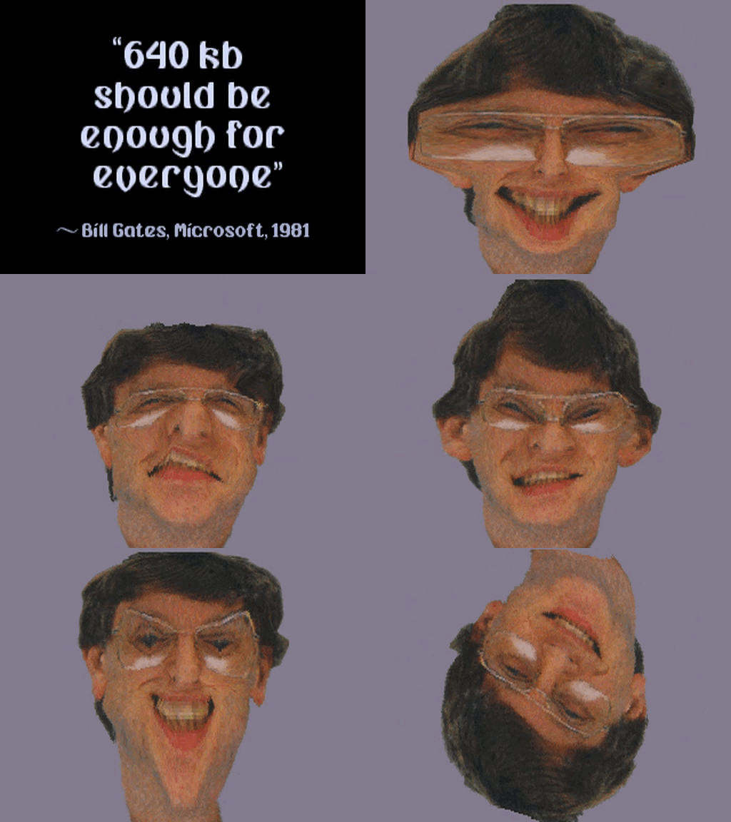
The GIF above is assembled directly from the six same-size 512x384
AVI-reference frames listed below. It is a compact view of the face-warp part,
not a local emulator capture.

Visible sequence:
01:48.000  quote scene enters from white/black transition
01:52.000  quote is legible over black, with the Bill face part about to enter
01:58.000  face source is visible against a flat grey-violet background
02:02.000  horizontal stretch dominates; features are pulled sideways
02:08.000  vertical squeeze/stretch takes over; head becomes tall and narrow
02:14.000  whirl phase; the face is twisted around its centre
02:20.000  tail/fade phase; the image is rotated/inverted and leaving the part


The resource names line up unusually cleanly:
xwarp.sci  file 0x01fe01  stored 0x007407  packed 1  target 0x00fd0a
xwarp.scr  file 0x027208  stored 0x00339b  packed 1  target 0x00918c
xwarp.sci is not raw 320x200 chunky data immediately after the resource
depacker. Its first bytes are:
52 49 58 33 40 01 c8 00 ...
R  I  X  3  width 0x0140  height 0x00c8
So the still image is a RIX-style 320x200 picture resource. The table target of
0x00fd0a fits "picture plus small header", not a naked mode-13h page.
xwarp.scr begins with small little-endian dwords:
0a 00 00 00  09 00 00 00  44 00 00 00  62 00 00 00
6a 00 00 00  83 00 00 00  9a 00 00 00  ac 00 00 00
That looks more like a script, offset table, or frame/control stream than image
pixels. I would not call the .scr format fully decoded from this pass, but
the pair is almost certainly the face picture plus the time-varying warp
program for this part.
The visual effect is a 2D image remap, not a 3D polygon scene. The evidence is visible and structural:
- The source object is a single flat face image with a constant grey-violet background.
- The face keeps its texture identity while its sampling coordinates are stretched, squeezed, and rotated.
- The transformations pass through continuous field distortions rather than faceted geometry.
- The executable already contains low-resolution texture/warp loops and table
builders near
0x2005d..0x20671and0x2273c..0x22fxx.
A plausible inner loop for the face phase is therefore not "draw Bill as polygons", but "sample Bill through a moving coordinate field":
for each destination row:
    choose row mapping parameters for current frame
    compute starting source u/v or load them from a generated row table
    compute per-column du/dv or load per-column entries
    for each low-resolution output column:
        sx = mapped u, clipped or wrapped into the source picture
        sy = mapped v, clipped or wrapped into the source picture
        color = source[sy * 320 + sx]
        write color twice horizontally to VGA
        advance u/v or advance the map pointer
For the 0x2005d mapper already identified elsewhere in the executable, the
inner loop is concrete: it renders 100 rows, 80 iterations per row, two samples
per iteration, and duplicates each sample horizontally by copying the byte into
both halves of a word before writing to VGA. That exact routine is an affine
texture mapper, so I am not claiming it alone proves every xwarp frame. The
important point is the same low-resolution sampling strategy: build or update a
mapping field once per frame, then run a tight byte-sampling loop over the
screen.
The three visible phases correspond to different map generators:
horizontal stretch:
    sx = centre_x + (x - centre_x) * scale_x(y, t)
    sy = y + small_wave(x, y, t)

vertical squeeze/stretch:
    sx = centre_x + (x - centre_x) * scale_x(t)
    sy = centre_y + (y - centre_y) * scale_y(x, t)

whirl:
    dx = x - centre_x
    dy = y - centre_y
    radius = table_or_approx_sqrt(dx*dx + dy*dy)
    angle = atan_table(dx, dy) + twist(radius, t)
    sx = centre_x + cos(angle) * radius
    sy = centre_y + sin(angle) * radius
On a 486 this would be too expensive if computed literally with square roots and transcendentals per pixel. The demo's style points toward tables and fixed-point increments: precompute row bases, sine/cosine or angle tables, and per-frame deltas; then let the inner loop consume those tables with byte loads, adds, and VGA stores. That also explains why the face can move from stretch to whirl smoothly without changing source art. The source image stays the same; the sampling field changes.
Runtime-To-Code Concordance
The public AVI-derived GIF covers only the Bill Gates quote/face-warp passage, so it should be read as a runtime witness for that part rather than as proof of the whole demo. Within that scope, the visible sequence now has a reasonably direct chain from frame to binary structure:
01:48.000  quote part enters
           resources are consistent with xwarp.sci plus xwarp.scr, loaded by
           the overlay table path at 0x4c43 and RLE-depacked at 0x4e09 when
           the packed flag is set

01:52.000  quote is stable on screen
           presentation-style bulk drawing matches the text/grid renderer
           family around 0x211b8/0x21310 rather than BIOS text output

01:58.000  Bill source face is visible
           xwarp.sci begins as a RIX3 320x200 picture; this is the source
           image that the later remap keeps sampling

02:02.000  face becomes horizontally wide
           the effect is a coordinate-field remap: destination pixels keep
           source texture identity while sx changes faster than sy

02:08.000  face is vertically squeezed and stretched
           the same source art is reused with a different per-frame mapping
           field, most likely driven by the xwarp.scr control stream

02:14.000  whirl phase
           this corresponds to a radial/angle remap stage, table-driven in
           practice rather than per-pixel sqrt/atan math

02:20.000  tail/fade leaves the part
           palette streaming/fade code at 0x2022d explains how the part can
           disappear without repainting every source pixel into darker colors
The synchronization backbone for those visual states is the IRQ scheduler, not
a loose delay loop. The timer handler at 0x1d1a increments [0x0ae5], services
one-shot callbacks through [0x0b48]/[0x0b44], runs a persistent callback
through [0x0b40], and can update the CRTC start address from
[0x0b34]+[0x0b38]. That gives parts a shared frame/tick clock while still
letting a part install its own per-frame stepper.
The visible Bill part also matches the executable's resource and rendering
shape. xwarp.sci is a packed picture resource with a RIX3 header and
xwarp.scr is a packed control/script-like stream; both are exactly the kind
of pair the overlay loader resolves from the internal EMF! directory. After
loading, the runtime does not need to keep decoding file formats. It can hold a
320x200 source picture and feed it through a generated sampling map.
The low-resolution mapper at 0x2005d..0x20203 is the clearest recovered code
example of that strategy:
0x2005d..0x200d8  rotate/zoom four corner points through trig tables
0x200e5..0x20158  derive fixed-point row and column deltas
0x20183          choose the active VGA page at 0xa0000 - [0x18]
0x2019e          render 100 destination rows
0x201ad..0x20203 sample source rows and duplicate pixels into VGA words
0x2022d..0x202ac stream and mutate the DAC palette for fading
That routine should not be over-identified as "the entire Bill warp" without another control-flow pass, but it proves the important mechanism used by the binary: animated parts are built from fixed-point table generation, compact inner sampling loops, and DAC-side fades. The AVI frames show exactly the kind of continuous texture deformation such a system is designed to produce.
The later polygon material is a separate rendering family. The filled-object
engine around 0x30000..0x304d6 builds matrices, transforms vertices,
projects them, backface-culls faces, writes scanline edge tables, and fills
spans. That explains the NFO's gouraud/polygon credits, but it is not the right
mental model for the Bill Gates segment. The face-warp passage is image-space
resampling; the 3D cluster is object-space geometry.
Affine Texture Mapper / Ripple-Style Mapper
The routine beginning at 0x2005d builds four transformed corner points and
then fills a 160x100 low-resolution field into VGA memory as duplicated pixels.
The code uses fixed-point math and row/column deltas.
Corner transform:
0x2005d  ESI = 0, EBP = 4 corners
0x20064  ECX = angle index [0x1c728]
0x2006b  EAX = sin/cos table [0x1c738 + angle*4]
0x20072  imul corner_x
0x2007c  EAX = second trig table [0x1cb38 + angle*4]
0x20083  imul corner_y
0x2008b  combine/subtract terms for rotated x
0x2008d  multiply by zoom [0x1c72a]
0x20095  shrd EDX,EAX,7 for fixed-point rescale
0x20099  add x center [0x1c732]
0x2009f  store transformed x
The y component repeats the same pattern with swapped/additive terms and center
[0x1c72e].
Interpolation setup:
0x200e5  divide top-edge delta by 100 rows, store integer/fraction parts
0x20122  divide left-edge delta by 160 columns
0x2015f  load starting source u/v fixed-point pair
0x20183  add source row table base [0x1c220]
0x2018f  EDI = active page start * 4 + 0xa0000 - [0x18]
0x2019e  ECX = 100 destination rows
The inner mapper at 0x201a3:
for each of 100 rows:
    save row u/v and x/y accumulators
    ECX = 80 columns, because each iteration writes two duplicated pixels
    row_base = table[v]

0x201ad  EAX = row table for current v
0x201b4  advance v fraction by column delta
0x201c1  AL = texture[row_base + u]
0x201c4  advance u fraction by column delta
0x201cb  AH = AL
0x201d3  write AX to VGA

0x201d6  repeat a second sample/write
0x20200  EDI += 4
0x20203  loop for 80 iterations

    restore saved accumulators
    advance row edge fixed-point values
    loop for next row
The two samples per loop and AH=AL duplication write four VGA pixels per loop
as two 16-bit stores. The visible resolution is 160x100 doubled horizontally,
which is a common speed tradeoff for animated affine/warped textures on 486-era
VGA.
Palette fade for this cluster is at 0x2022d:
0x20236  ESI = current palette buffer
0x2023c  DX = 3c8h, AL = 0
0x20242  write DAC start index
0x20245  DX = 3c9h
0x2024a  output 3 bytes per color, 255 colors
0x20271  EDX = 63 * fade_step / 64
0x20280  EBX = 64 - fade_step
0x20297  ECX = 0x2fd bytes
0x2029e  AL = source byte
0x2029f  AL = AL * EBX / 64
0x202a5  add EDL bias
0x202a7  store into active palette
This fades by mutating a palette buffer, then streaming it to the DAC every tick, rather than by touching the framebuffer.
3D/Gouraud/Polygon Engine
The 3D cluster around 0x30000 contains a conventional but well-optimized
protected-mode software renderer.
Rotation Matrix
The first routine computes a 3x3 matrix from trig tables:
0x3000c  load trig table value from 0x2aa1c[angle]
0x3001c  load paired trig value from 0x2ab84[angle]
0x30025  signed multiply table terms
0x3002d  shrd EDX,EAX,10h to keep fixed-point high result
0x30031  keep partial product in EBX
0x30033  multiply/add second term
0x30053  store matrix coefficient at 0x27184
The coefficients land at 0x2716c..0x2718c.
Vertex Transform
0x300ab applies the matrix to a point array:
for each point:
    x' = m00*x + m01*y + m02*z
    y' = m10*x + m11*y + m12*z
    z' = m20*x + m21*y + m22*z
    ESI += 0x10
    EDI += 0x10
The multiply/add sequence is explicit:
0x300bc  imul [ESI+0] by m00
0x300be  imul [ESI+4] by m01 into EBX
0x300c2  imul [ESI+8] by m02 into ECX
0x300c6  add EBX
0x300c8  add ECX
0x300ca  store transformed x
Projection
0x3011a projects transformed points to screen coordinates:
0x3011a  ECX = z
0x30125  z += [0x2b8d0]
0x30127  z += 0x320000
0x3012d  EBX = 0x180, x scale
0x30132  imul x by scale
0x30134  idiv z
0x30136  add screen center x [0x2b8c8]
0x3013c  store projected x
0x30141  EBX = 0x140, y scale
0x30146  imul y
0x30148  idiv z
0x3014a  add screen center y [0x2b8cc]
This is normal perspective division. The large 0x320000 bias keeps the
denominator positive and prevents near-plane singularities for the intended
object ranges.
Backface Test
0x3015d computes a signed 2D area for each face:
dx1 = x[v_b] - x[v_a]
dy2 = y[v_c] - y[v_a]
term1 = dx1 * dy2

dy1 = y[v_b] - y[v_a]
dx2 = x[v_c] - x[v_a]
term2 = dy1 * dx2

visible = (term1 - term2) > 0
The result is written as a byte flag at face+1. A negative or zero area marks
the face as hidden.
Triangle/Quad Handling
0x301cb walks face records:
0x301cb  EDX = face flags/color
0x301cd  if DH has sign bit set, skip face
0x301d3  store face color to 0x271b4
0x301d9  EBP = vertex count / polygon type
0x301dc  load up to four vertex indices
0x301e8  map indices through projected coordinate pointer table at 0x2b670
0x30204  call polygon setup
0x3020b  advance face record by 0x20
At 0x30212, all vertex y values are biased by 0x03200000 before the edge
sort. The polygon is then split into one or two triangles:
0x30240  if EBP == 3, only draw triangle (a,b,c)
0x30245  otherwise draw triangle (a,c,d)
0x30260  then draw triangle (a,b,c)
Edge Table
0x30286 sorts the three y coordinates, stores them at 0x271cc, and turns
them into 16.16 fixed-point edge walkers:
0x3028b  sort y0, y1, y2 by exchange
0x3029b  store sorted y values
0x302a4  shift y values left by 16
0x302d1  delta_y long edge = y2 - y0
0x302e1  delta_x long edge = x2 - x0
0x302f5  slope_long = delta_y / delta_x
0x30301  compute upper edge slope
0x3033d  compute lower edge slope
The code chooses which pair of slopes is left/right by comparing them:
0x30374  compare ECX and EDX slopes
0x30378  xchg if needed
0x30383  call 0x30415 to write spans
0x30415 is the edge-table writer:
0x30415  if current left bound is greater, replace it
0x3041b  if current right bound is smaller, replace it
0x30423  advance left by slope
0x30425  advance right by slope
0x30427  advance edge-table pointer by 8
0x3042a  loop for scanline count
Span Filler
0x3042e walks 200 scanlines of generated left/right spans:
0x30443  EDX = 200 rows
0x30448  EBP = framebuffer base table [0x2d134] + 0x61ac0
0x30454  ESI = left x, EDI = right x
0x30459  convert 16.16 x values to integer
0x3045f  clip left/right to 0..319
0x30483  if right >= left, call span writer
0x3048c  reset span to sentinel values
0x30499  EBP += 320 for next scanline
0x304a6 is the optimized horizontal fill:
0x304a6  EBX = right - left + 1
0x304ad  if length < 12, use byte-only fill
0x304b2  load packed color dword from 0x271b4
0x304ba  EDI = framebuffer_row + left
0x304be  compute bytes needed to align EDI to dword
0x304c8  rep stosb for leading unaligned pixels
0x304ca  ECX = remaining / 4
0x304cf  rep stosd for middle
0x304d1  EBX &= 3
0x304d6  rep stosb for trailing pixels
This is not merely a wireframe effect. It has a full filled-polygon pipeline: matrix build, point transform, perspective projection, backface culling, edge building, clipping, and aligned span writes. The NFO's "gouraud routines" credit matches this cluster, although this specific span routine is a flat-color fill; the broader object system likely switches span routines through dispatch tables.
Twister / Planar VGA Copy Cluster
The cluster around 0x59c70 handles an unchained or planar-ish VGA part. It
uses direct sequencer/graphics-controller writes plus a ring buffer.
Initial transfer:
0x59c74  DX = 3c4h, AX = 0f02h, enable all plane masks
0x59c7e  EDI = [0x586c8] + 0xa0000 - [0x18] + 7
0x59c93  ESI = current source pointer [0x58724]
0x59c99  EBP = 0x28 rows
0x59c9e  call 0x59d2d
0x59d2d copies a vertical stripe:
0x59d2d  ECX = 16
0x59d32  rep movsb, copy 16 source bytes
0x59d34  wrap source pointer if it reaches end [0x586c4]
0x59d42  EDI += 0x94
0x59d48  loop EBP times
The stride 0x94 is 148 bytes, not the standard 80 or 320. Combined with the
part's starting offsets and plane masks, that produces a skewed/twisted copy
pattern rather than a linear bitmap blit.
The center bands use specialized nibble/byte selectors chosen by [0x58728]:
0x59d4c  read mode byte
0x59d58  mode 0 -> 0x59db8
0x59d63  mode 1 -> 0x59df4
0x59d6e  mode 2 -> 0x59e2c
0x59d79  mode 3 -> 0x59d80
Each mode copies eight visible bytes per row, but with a different phase:
mode 3: add 2 to source/dest, copy 2, skip 2, copy 2...
mode 0: start one byte later, copy pairs, then back up one byte at row end
mode 1: copy pairs from the current alignment
mode 2: copy 1, skip 2, copy pairs, then copy a final byte
So the part is not just copying a picture. It is changing which plane/phase lands on the screen for each band, creating an interleaved twisting motion.
The vertical line insertion/erase at 0x59e64 uses graphics-controller write
mode:
0x59e64  select GC register 5 at 3ceh
0x59e6b  read current value
0x59e6d  OR AH with 1, write mode control back
0x59e72  sequencer map mask all planes
0x59e7c  EDI = active VGA base + 0x2058
0x59eb0  loop 100 times copying one byte every source +0x27, dest +0xa3
0x59ec2  back source by 0x0fa0 and dest by 0x4064
0x59ed3  draw second 100-byte column
0x59f0b  clear write-mode bits again
0x59f20  erase/zero vertical path every 0xa3 bytes
This is classic VGA-plane trickery: a small number of CPU writes are expanded by the VGA latch/plane hardware into visible columns or masks.
Twister Palette Fades
The same part uses a compact 96-color palette. Palette upload:
0x5a220  DX = 3c8h, AL = 0
0x5a226  write DAC start index
0x5a227  DX = 3c9h
0x5a229  EBP = 0x60 colors
0x5a22e  ECX = 3
0x5a233  rep outsb for one RGB triplet
0x5a235  loop 96 colors
Fade-in at 0x5a211:
0x5a253  EBX = 64 - fade_step
0x5a25e  ESI = original palette at 0x58735
0x5a263  EDI = working palette buffer [0x586bc]
0x5a269  ECX = 0x120 bytes
0x5a270  AL = source component
0x5a271  AL = AL * EBX / 64
0x5a277  write component
0x5a27b  fade_step++
Fade-out/invert at 0x5a282 does three interleaved passes over R, G, and B
components:
0x5a2c8  EDX = 0x3d * fade_step / 64 for first channel
0x5a2e2  process 96 components with stride 2 in source/dest
0x5a2fc  EDX = 0x3b * fade_step / 64 for second channel
0x5a318  same loop, starting one byte later
0x5a332  EDX = 0x38 * fade_step / 64 for third channel
0x5a352  same loop, starting two bytes later
0x5a36c  fade_step--
That gives each RGB channel a slightly different destination bias (0x3d,
0x3b, 0x38), so the fade is colored rather than a purely gray fade.
End Logo / Bitmap Conversion
The setup around 0x5a0b3 converts chunky data into planar VGA:
0x5a0b3  clear graphics-controller write mode bits
0x5a0c1  AX = 1102h, initial sequencer map mask value
0x5a0c5  EBP = 4 planes
0x5a0ca  out AX to 3c4h
0x5a0d0  save source/dest/count
0x5a0d3  movsb one byte, then source += 3
0x5a0d7  loop over byte count
0x5a0dd  ESI++ to move to next chunky byte phase
0x5a0de  rol AH,1 to rotate the plane mask
0x5a0e0  repeat for four planes
This is a chunky-to-planar splitter. It walks the same chunky source four times, copying every fourth byte into a different plane by rotating the sequencer map mask.
What Verses Is Doing
Verses is a mature 1994 protected-mode PC demo. Its core technical shape is:
- A single executable with a custom PMODE-based runtime and embedded resource directory.
- A simple internal RLE/literal resource depacker for packed screens and data.
- Direct GUS support driven from
ULTRASND, with no Sound Blaster fallback. - Timer-driven part scheduling through IRQ callbacks.
- Direct VGA programming: DAC streaming, CRTC page/scroll writes, sequencer
masks, graphics-controller write mode, and linear protected-mode writes to
0xa0000. - Multiple classes of inner loops: bulk
rep movsdtext/glyph copy, low-res affine texture mapping, planar twister copies, palette-space fades, and a full 3D filled-polygon pipeline. - A script/image-driven Bill Gates quote and face-warp part using
xwarp.sciandxwarp.scr, where the visible work is a moving 2D coordinate remap rather than a polygon pass.
The demo's "fancy" feel is not coming from one miracle routine. It is the combination of protected-mode memory freedom, embedded resources, a callback driven runtime, and several small inner loops that are each specialized for one visual job.