Analysis model: gpt-5.5 xhigh
The Sea Robot of Love by Orange - Technical Dissection
Scope
This is a binary-level pass over The Sea Robot of Love by Orange, released in 1995 for MS-DOS.
Useful public references:
- Scene.org party archive: https://files.scene.org/view/parties/1995/theparty95/in64/okean.zip
- Scene.org Orange archive: https://files.scene.org/view/demos/groups/orange/okean.zip
- Hornet mirror archive: https://files.scene.org/view/mirrors/hornet/demos/1995/o/okean.zip
- The Party 1995 results: https://files.scene.org/view/parties/1995/theparty95/results.txt
The included text identifies the intro as The sea robot of love!, says a
386 is required, says a GUS may be used for sound, and documents the -M
parameter for monitors that dislike the default 50 Hz VGA mode. It credits
programming to Hoplite and Dune, sound effects and music to Dune, font and
graphics to Der Piipo, PMODE to Tran, player code to Phantom, and the 50 Hz
mode to Liket. Old reachability details in the text file are intentionally not
repeated here.
The important technical shape is: a tiny MZ/RNC shell expands a much larger
PMODE runtime; the runtime enters a custom mode-13h-derived 50 Hz VGA mode
unless -M is supplied; each part renders into a 320x200 chunky offscreen
buffer; most presentation is a timed sequence of additive line splats, grid or
height-field projections, palette fades, and a final masked font renderer.
Examined Archive
The competition archive used for this pass:
518e93a4eca82f3b822134736b747c1af1ecace8dcd258cb3aad86f73e358488 okean.zip
Extracted files:
138fea04ea65e9d13e360fd27d91c671190c60624d0035374ae74bd84dd28e96  FILE_ID.DIZ
1c97667b739e206df4eae02495b3df3bac2d254799d4c24aa59c81197449b708  INFOFILE
a18d2212b1b95eb153a9b7709154da9614698bf4c3d88df74b420befd4fdef64  KORSO2.EXE
The public Hornet, party, and Orange-group archives differ as zip containers,
but the executable payload examined here is the same KORSO2.EXE in the party
archive.
KORSO2.EXE is a 65,358-byte DOS MZ executable:
file size:                 65358 bytes
MZ header:                    32 bytes
relocations:                   0
minalloc/maxalloc:         17954 / 65535 paragraphs
entry:                    0fc5:000c
stack:                    5422:04de
RNC marker:               file offset 0x20
Unpacking the RNC block at file offset 0x20 gives the real runtime image:
RNC method:                    1
packed payload:            64563 bytes
unpacked payload:         345399 bytes
unpacked hash:
d484339fc87d3566e677b2bb65bddf8e8c6d860d02e81d5ae1715a274bd0fa2e
The unpacked image starts directly with PMODE/runtime material, not with a second MZ header. The visible strings at the front include the standard PMODE failure messages:
386 or better not detected!!!
System is already in V86 mode, and no VCPI or DPMI found!!!
Not enough extended memory!!!
Couldn't enable A20 gate!!!
DPMI host is not 32bit!!!
Couldn't enter 32bit protected mode!!!
That is enough to classify the file as a compact DOS-facing RNC loader around a protected-mode intro image.
Runtime Capture
A DOSBox-X 2026.01.02 runtime capture on 19 June 2026 used the original
KORSO2.EXE from the party archive, GUS enabled at ULTRASND=240,3,3,5,5,
and the intro's default display path. The -M monitor-safe option was not used
for this pass, so the captured run follows the custom 50 Hz mode setup
described below. Timing zero is the start of the capture stream, including the
DOSBox-X shell. The program exited normally, and the recorded stream is 188.25
seconds long.
The sequence GIF below is assembled directly from the ten published DOSBox-X runtime frames. It summarizes the visual path through the noisy title image, red additive line scenes, green mesh, red ring/column mesh, blue height field, magenta star/title section, late text renderer, and final credit screen.
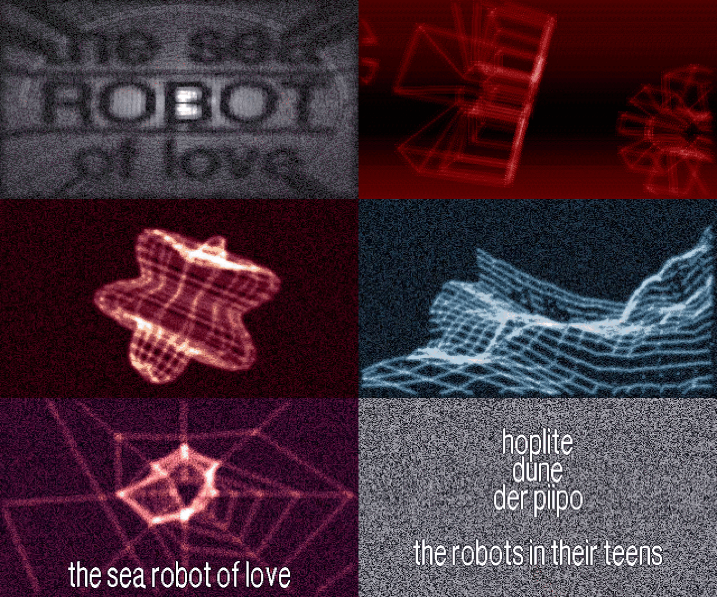
At 00:09.000, the opening has settled into the noisy gray title image. This
is the first clear statement of the production identity before the renderer
switches to the red additive line sections.
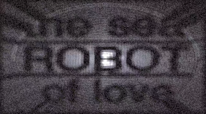
At 00:15.000, the intro is already in a red line/splat phase. The visible
shape is mostly wire and glow, which matches the recurring additive line
primitive described later: lines are sampled into a chunky buffer with small
brightness stamps rather than drawn as plain one-pixel edges.
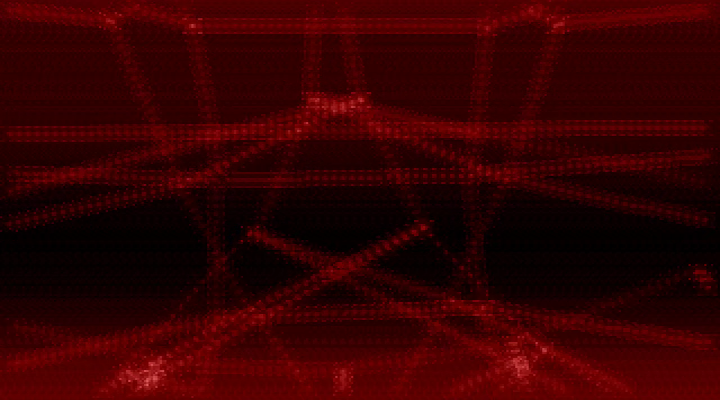
At 00:30.000, the red section has become a clearer segment-and-object scene.
This anchors the early stripe/segment part: broad horizontal bands sit behind
wire objects that slide and rotate through the frame.

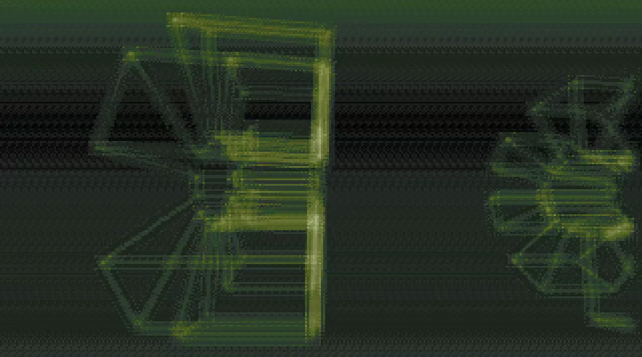
At 00:48.000, the palette has moved to green and the geometry reads as a
larger mesh. The screenshot is useful because it shows the intro's repeated
habit: build compact point/edge data, project it, and let the additive drawing
make it look larger and softer than the stored model.
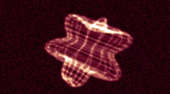
At 01:15.000, the ring/column mesh is fully legible. The red wire surface and
bright highlight are a good visual counterpart to the ring/column part at
0x3d79a, where compact generated geometry is turned into a glowing layered
form.
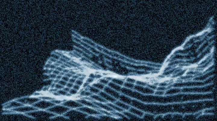
At 01:45.000, the blue height-field section is active and the captioned
light/shadow phrase is on screen. This is the clearest still for the later
height-field and moving-light parts: a sine-built mesh, a noisy background, and
text all share the same full-frame presentation path.
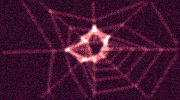
At 02:11.000, the magenta star-like mesh section has taken over. The geometry
is simpler than the height field, but the same additive glow gives the points
and edges a soft, overexposed center.
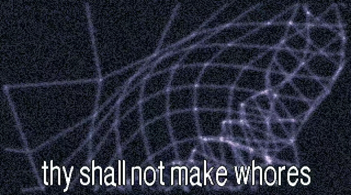
At 02:15.000, the intro prints the sea robot of love over the magenta mesh.
This frame ties the abstract geometry back to the title instead of leaving the
middle of the run as a sequence of anonymous wire forms.

At 02:39.000, the ending text renderer is active over the blue mesh. The
section uses the custom masked proportional font path described near the end of
the analysis, still copying through the same chunky framebuffer pipeline.
At 02:51.000, the credit text is visible on the noisy gray background. This
late frame closes the runtime sequence: after the additive geometry and mesh
sections, the intro returns to text as the final public-facing layer.

Runtime-To-Code Concordance
The sequence GIF is an overview index for the ten frame anchors; the stronger mapping is the per-frame relationship to the protected-mode part calls:
sea-robot-runtime-00-09-000.pngmaps to the startup/display setup and early presentation state: RNC/PMODE entry, the custom 50 Hz mode-13h-derived VGA setup, shared table/allocation setup around0x39329, and the 64,000-byte chunky-to-A000 copy pattern used by later parts.00-15-000.pngmaps to the opening sine-line/additive-buffer part at0x2d12f, including sine table expansion, low-bit noise fill, additive line splats, and the timer/player callback path.00-30-000.pngmaps to the stripe/segment part at0x2f639, where row-ramp background generation, segment tables, overlay line passes, and palette blending create the red banded wire scene.00-48-000.pngmaps to the grid/mesh line part at0x376a5, especially the generated edge tables, deformed vertex grid, projected line drawing, and timed palette/phase updates.01-15-000.pngmaps to the ring/column mesh part at0x3d79a, where compact generated geometry is projected into the glowing red column/ring form.01-45-000.pngmaps to the rotating height-field/edge part at0x5420f, including sine-built mesh data, noisy framebuffer background, moving-light presentation, and blended palette/text overlays.02-11-000.pngand02-15-000.pngmap to the larger mesh/table-line stage around0x393e0and its title overlay handoff. These frames are runtime evidence for the abstract magenta mesh being reused as a title carrier, not a separate bitmap title card.02-39-000.pngand02-51-000.pngmap to the final text part at0x4e230, where the masked proportional font path and palette fade logic return the show from additive geometry to readable credits.
The bounded claim is important: the GIF proves the observed timeline through the major visual stages, while the detailed sections below explain the render mechanics from code. It does not by itself prove GUS playback behavior; audio and timer/player callbacks are code evidence in this pass.
Startup And The 50 Hz Mode
The top-level protected-mode driver is around raw offset 0x10f89. It first
sets ordinary BIOS mode 13h through PMODE's real-mode interrupt bridge:
mov word [0e0h], 0013h
mov al, 10h
int 33h
As in several other Tran PMODE runtimes, int 33h here is not mouse logic.
The caller fills a small real-mode register block, puts the target interrupt
number in AL, and executes the bridge. The bridge then performs the BIOS or
DOS interrupt from protected mode.
Immediately after the mode set, the driver scans the command line for M or
m. If either is found, it skips the custom timing block. Without -M, it
rewrites VGA timing registers:
Misc output 3C2h = 63h

CRTC 00 = 60   CRTC 01 = 4f   CRTC 02 = 50   CRTC 03 = 82
CRTC 04 = 54   CRTC 05 = 80   CRTC 06 = 6f   CRTC 07 = 3e
CRTC 08 = 00   CRTC 09 = 41   CRTC 10 = f6   CRTC 11 = 88
CRTC 12 = 8f   CRTC 13 = 28   CRTC 14 = 40   CRTC 15 = 90
CRTC 16 = 6c   CRTC 17 = a3

Sequencer 01 = 01
Sequencer 03 = 00
Sequencer 04 = 0e

Controller writes seen through 3C3h/3C4h area:
  4005h
  0506h
The first CRTC write unlocks register 11h; after that the code writes a full
register table. The selected display is still treated by the effect code as a
320x200 byte framebuffer, but it is not merely BIOS mode 13h. The intro wants
a 50 Hz refresh cadence, and the runtime has timer code that calibrates against
that cadence.
On exit, the driver returns to BIOS text mode 3 through the same bridge and then unmasks the PIC:
mov word [0e0h], 0003h
mov al, 10h
int 33h
out 21h, 0
Shared Timing, Buffers, And Presentation
The local allocator is at 0x1179. Callers put the byte count in EAX and
receive a pointer in EAX. Most effect entries allocate one or more work
buffers:
0xfa00 bytes   exactly one 320x200 chunky page
0xfa05 bytes   one 320x200 page plus padding for alignment
0x1800 bytes   compact point/edge work tables
0x10000 bytes  64K-aligned table area
0x20000 bytes  128K table area
0x80000 bytes  large edge/mesh scratch space
0x100000 bytes very large mesh/work table
The visible screen update pattern is the same in many parts:
mov edi, 0a0000h
sub edi, [18h]       ; PMODE linear mapping adjustment
mov esi, framebuf
mov ecx, 3e80h       ; 0x3e80 dwords = 64000 bytes
rep movsd
So the heavy drawing is normally offscreen. VGA memory receives a final 64,000-byte copy after the frame has been built and after retrace/timer work has been done.
The timer routines are duplicated per section rather than centralized in one small library. One representative set is:
0x15aac  install timer IRQ/vector through PMODE callbacks
0x15b00  restore previous vector and PIT mode
0x15b27  calibrate PIT reload against port 3DAh retrace bit
0x15b76  IRQ body: adjust reload, wait edge, call visual/music callback, EOI
The calibration routine writes PIT control value 30h to port 43h, waits on
the VGA status port 3DAh, reads the PIT counter through port 40h, then
stores a reload word. The IRQ body repeats the retrace sampling, writes the
next low/high PIT reload bytes to port 40h, calls a callback pointer, and
acknowledges the PIC.
Several effects contain local copies of the same pattern around offsets such
as 0x2d43c, 0x367cc, and 0x39aac. That duplication is important: the
sections are not independent executables, but they do carry their own timer
state and phase variables.
The top-level visual sequence is straightforward:
0x39329  shared table/allocation setup
0x2d12f  opening sine-line/additive-buffer part
0x2f639  stripe background plus segment/line overlay
0x3640b  height/table morph part
0x376a5  3D grid/mesh line part
0x393e0  larger mesh/table line part
0x3d79a  ring/column mesh part
0x5420f  rotating height-field/edge part
0x4e230  final text part
Between calls, the driver tests keyboard port 60h for Esc scan code 01h.
That test is also repeated inside the longer sections.
The Additive Line/Splat Primitive
A recurring inner loop does not plot single-pixel Bresenham lines. It draws a fixed-point line, and at each sample it adds a small multi-row brightness stamp into the chunky framebuffer.
The mesh line renderer around 0x37290 is the clearest version. It receives
two projected endpoints, sorts them by y, and computes fixed-point deltas:
steps = y1 - y0
dx = ((x1 - x0) << 8) / steps
dy = ((y1 - y0) << 8) / steps
x  = x0 << 8
y  = y0 << 8
It clips to an inset rectangle:
x range: 0 .. 0x137   ; 0 .. 311
y range: 0 .. 0x0bf   ; 0 .. 191
The clipping rectangle is smaller than 320x200 because the plotter writes a wide/tall stamp around the current sample. Keeping the center inside this range keeps the stamp inside the buffer.
The fast path avoids per-sample clip tests when both endpoints are already inside the valid rectangle. It computes the byte address directly:
dst = framebuf + y * 320 + x
The clipped path uses a prebuilt row lookup table:
dst = framebuf + row_ptr[y] + x
At each sample, the renderer adds a shaped brightness pattern with unrolled dword writes. The values are byte-parallel intensity increments:
row -0: add 0001010100h around the center
row +1: add 02020101h
row +2: add 08040201h
row +3: add 08060201h
row +4: add 08060201h
row +5: add 08040201h
row +6: add 02020101h
row +7: add 0001010100h
The code writes both the left and right halves with +4 dword offsets, so the
stamp is wider than one dword. Then it advances:
x += dx
y += dy
repeat until the line is complete
This explains the visual character of several parts: they are line networks,
but the line is a small additive glow stamp, not a thin vector line. The code
uses integer add into dwords, so each byte lane accumulates brightness by
ordinary 8-bit wrap behavior inside the dword addition. The palette and the
low-amplitude noisy background keep that from reading as plain aliased line
art.
The earlier line routines around 0x2cb3c and 0x2cfb9 use the same idea
with slightly different constants. They also sort endpoints, compute
fixed-point deltas, clip to the same inset rectangle, and add a multi-row
pattern into a chunky buffer.
Opening Sine-Line Part At 0x2d12f
The first visual part starts by extending sine/cosine tables. A source table at
0x24a3c is copied and negated into a wraparound table at 0x25a40:
copy 0x400 dwords backward into 0x25a40
copy 0x800 dwords as negated values into 0x25a40 + 0x1000
copy 0x400 dwords forward into 0x25a40 + 0x3000
That gives the effect cheap positive, negative, sine, and cosine samples with masked indices instead of branch-heavy quadrant logic.
The part allocates a 64,000-byte framebuffer at 0x29a58, installs a timer,
writes a palette from 0x2b65c, and enters its frame loop.
Point Builder
Each frame builds 256 point records at 0x29a5c. The loop uses two global
phase indices, one for the base phase and one for the scale phase:
scale = sine[scale_index] + 0x400
i = point_phase

for 256 points:
    sx = sine[i]
    sy = cosine[i]

    x = (((sx * 3) / 2) * scale >> 11) + x_base
    y = (sy * scale >> 11) + y_base

    store x,y into the point record
    i = (i + 0x10) & 0xfff
That is not a perspective transform yet. It is building a moving 2D/parametric shape whose radius itself breathes through another sine channel.
Background Fill
Before drawing the lines, the section fills the whole offscreen page with a deterministic low-bit noise pattern:
for 0x3e80 dwords:
    out = seed & 0x07070707
    *dst++ = out
    seed += 0x9d
    seed = ror(seed, 11)
    seed ^= 0x9d
The mask keeps only small intensity bits in each pixel byte. It is a cheap grain/floor for the additive line stamps.
Line Pass
The call to 0x2cfb9 iterates the 256 point records. It creates projected
screen coordinates in a temporary table near 0x2a65c, adds center offsets
0xa0 and 0x64, and connects records with the additive line primitive. One
path also draws lines toward the screen center.
The hot line routine at 0x2cb3c does:
sort endpoints by y
compute fixed-point dx/dy
if both endpoints are safely inside 0..311,0..191:
    use the fast unguarded stamp loop
else:
    use the clipped stamp loop
for each sample:
    dst = framebuf + y * 320 + x
    add a small unrolled brightness stamp
    x += dx
    y += dy
After the draw, the part calls the player/tick callback through 0x4d98c,
waits for the retrace/timer point, optionally fades the palette once the phase
state crosses a threshold, copies the offscreen page to VGA, and loops.
Phase Update
The phase update routine around 0x2d33b is driven by the timer state:
if 50 Hz mode is active:
    accumulate local ticks
    every fourth tick, increment the global frame word

advance part state at frame thresholds 0x40 and 0x30
scale_index += 4
point_phase += 1
mask both with 0x0fff
write shared phase constants near 0x24a2c
The result is a line object whose geometry and brightness evolve from a few sine indices, not from precomputed animation frames.
Stripe And Segment Part At 0x2f639
The next section sets its stage flag to 2, clears the visible screen, allocates
an aligned 64,000-byte buffer at 0x2cae0, writes a palette from 0x2d9e4,
builds several vertex/segment tables, and installs a local timer.
The setup loop builds eight groups of records using the sine tables. It stores
positive and negative depth variants, including records with +0x400 and
-0x400 z-style values. Those tables are then used by the per-frame segment
draws.
Row Ramp Builder
At the start of each frame, the code creates a 200-byte row table at 0x2c9c8:
phase1 = global_phase_a
phase2 = global_phase_b

for y in 0..199:
    row = ((sine[phase1] + 0x400) >> 6)
        + ((sine[phase2] + 0x400) >> 8)
    table[y] = row
    phase1 += step_a
    phase2 += step_b
Fullscreen Fill
The framebuffer fill converts each row byte into a replicated dword:
for each of 200 rows:
    value = row_table[y]
    pixel4 = value * 0x01010101
    grain = seed & 0x03030303
    eax = pixel4 + grain

    repeat 0x50 times:
        *dst++ = eax       ; 0x50 dwords = 320 bytes
This is the horizontal banded background. The dword replication is the whole trick: one integer multiply creates four identical chunky pixels.
Overlay And Palette Mix
Depending on the stage counter, the section calls the overlay renderer either
eight times with a phase step of 0x1ff or five times while advancing a larger
vertical/shape offset. The called routine around 0x2f4b5 consumes the record
tables prepared at entry and draws into the same offscreen page.
When the global phase reaches the later state, the section blends two 768-byte palettes:
for each RGB byte:
    out = (palette_a[i] * factor_a + palette_b[i] * factor_b) >> 11
It then writes the result to the DAC, copies the page to VGA, and continues until the shared stage word reaches 7 or Esc is pressed.
Height/Table Morph Part At 0x3640b
This section copies a 768-byte palette from 0x347a8 to a work area at
0x2ef1c, allocates a 64,000-byte buffer at 0x2ff9c, writes the palette, and
installs another local timer.
The strongest inner loop here builds a 16x16 height table at 0x2ffa8.
Each record receives a z/height value derived from an input byte:
for 16 rows:
    for 16 columns:
        if the point is on the border:
            z = 0x800
        else:
            z = -0x400 + input_byte * 8
        store z in the point record
The forced border value makes the grid edge behave differently from the interior and avoids edge collapse during projection.
The framebuffer fill is another masked-noise pass, this time with a wider per-byte mask:
for 0x3e80 dwords:
    *dst++ = seed & 0x0f0f0f0f
    seed += 0x9d
    seed = ror(seed, 11)
    seed ^= 0x9d
Per-frame sine values are written into globals such as 0x2ff58, 0x2ff5c,
and 0x2ff4c, then the renderer at 0x3627e projects/draws the current table.
The visible transition uses a 768-byte palette blend:
for each RGB byte:
    out = (palette_a[i] * factor_a + palette_b[i] * factor_b) >> 7
The smaller shift means the factors here are scaled differently from the later
stripe fade. The section exits when its state reaches 0x0b.
Grid/Mesh Line Part At 0x376a5
This part is the best self-contained example of the intro's mesh renderer. Entry allocates five blocks:
0xfa10 bytes  aligned framebuffer
0x1800 bytes  source vertex grid
0x1800 bytes  deformed vertex grid
0x80000 bytes edge/index work area
0x1000 bytes  row/table scratch
Edge Table
The code first builds an edge table in the large work area. One loop emits pairs for adjacent points in one direction:
for 32 rows:
    for 16 columns:
        emit edge(point[row][col], point[row][col+1])
A second loop emits pairs in the other direction, using 16-by-30 style bounds and record offsets based on 12-byte vertex records. The exact table format is not a high-level scene graph; it is a compact list of byte offsets into vertex records. The render pass later reads these offsets and calls the line stamp routine for each pair.
Base Vertex Grid
The source grid builder creates 32 by 16 points. Each point is a 12-byte
record, effectively three 32-bit coordinates. It walks a sine/cosine phase by
0x100 per column:
for each row:
    row_sine = sine[row_phase]
    for each column:
        x = sine[col_phase]   * row_sine >> 10
        y = cosine[col_phase] * row_sine >> 10
        z = row_depth
        store x,y,z
        col_phase += 0x100
That produces a structured circular/cylindrical mesh table without storing a full model in the archive.
Per-Frame Deformation
Each frame starts with the same low-intensity noise page:
*dst++ = seed & 0x0f0f0f0f
Then it creates a deformed copy of the source grid:
for 32 rows:
    row_scale = 0x200 + (sine[row_phase] >> 3)

    for 16 columns:
        wobble = (sine[col_phase] >> 4) + row_scale

        out.x = in.x * wobble >> 9
        out.y = in.y * wobble >> 9
        out.z = in.z * wobble >> 9

        advance column phase
The renderer then walks the edge list. For each edge:
v0 = deformed_vertices + edge.offset0
v1 = deformed_vertices + edge.offset1
project/prepare endpoints
call 0x37290 line stamp renderer
This is why the line primitive matters. The mesh itself is modest, but every edge is rendered as a multi-pixel additive stroke, so the final part looks much denser than a raw edge count would suggest.
Large Mesh Setup At 0x39329 And 0x393e0
The call at 0x39329 happens before the first visual section. It prepares
shared table storage for later mesh parts:
allocate 0x20000 bytes
align pointer upward to the next 64K boundary
store aligned base at 0x37148

allocate 0x10000 bytes
store at 0x371b4

patch many globals in the 0x3751c..0x37752 range to point into the table block
call 0x3839a and 0x38672 to initialize derived tables
This is one of the reasons the executable feels more integrated than a chain of independent parts. The early setup call patches pointer constants for later renderers, then the visual calls reuse those tables.
The later part at 0x393e0 allocates larger work areas:
0x3000 bytes   vertex/grid table
0x100000 bytes edge/work table
0x3000 bytes   transformed table
0x1f10 bytes   extra point table
0x1f10 bytes   extra point table
It builds a 32x32 grid of 12-byte records. The coordinate initializer starts
around -0x1000 and steps by 0x100, storing a regular lattice. It also
creates two edge lists: one for horizontal-ish neighbor pairs and one for
vertical-ish neighbor pairs. Each edge uses offsets into the 12-byte point
records, just like the smaller grid part.
The practical effect is a bigger mesh/table renderer using the same vocabulary: regular procedural grid, transformed point copy, edge-offset list, additive line draw, timed palette and phase updates.
Ring/Column Mesh Part At 0x3d79a
This section allocates a 64,000-byte framebuffer at 0x38e00 and builds a
compact point table with 16 rows and 8 columns. The entry builder creates
records from sine/cosine samples:
for 16 rows:
    y = row_depth
    for 8 columns:
        x = 5 * sine[col_phase]
        z = 5 * cosine[col_phase]
        store x,y,z
        col_phase advances around the circle
Per frame, it constructs a transformed version of that table:
for each row/column:
    scale = per-column or per-row sine-derived value
    out.x = sine[col_phase]   * scale >> 8
    out.z = cosine[col_phase] * scale >> 8
    out.y = row_depth
The background fill uses a stronger low-bit mask:
for 0x3e80 dwords:
    *dst++ = seed & 0x1f1f1f1f
    seed += 0x9d
    seed = rol(seed, 11)
    seed ^= 0x9d
Three sine indices produce dynamic globals such as 0x38dbc and 0x38dcc,
then the renderer at 0x3d675 draws the transformed shape. The section calls
the music/tick path, waits for retrace, writes palette bytes from 0x3be28,
copies the page to VGA, and exits when the stage reaches 0x17.
The code behavior is again a generated point set plus a renderer, not an animation stream.
Rotating Height-Field Part At 0x5420f
The section at 0x5420f allocates its render buffer at 0x4dec1, writes a
palette from 0x526cd, installs its local timing helpers, and builds a 16x16
field table at 0x4decd.
The field generator is direct and useful:
for y from -64 to +56 step 8:
    for x from -64 to +56 step 8:
        r2 = x*x + y*y + phase
        idx = r2 & 0x0fff
        z = sine[idx] * amplitude >> 9
        store x,y,z
That is a radial sine height field. It needs only a grid and a sine table; the
wave shape follows from x*x + y*y.
The projection routine at 0x540be loops over all 256 records. It applies
three rotation-like transforms using sine and cosine tables, then projects with
a divide:
for each point:
    rotate x/y/z through three sine/cosine stages

    screen_x = 0xa0 + ((x << 8) / z)
    screen_y = 0x64 + ((y << 8) / z)

    if z <= 0:
        use the fallback multiply/guard path

    store projected point at 0x4f9cd
After projection, the renderer walks 0x1e0 edge records from 0x4eacd. Each
edge maps two point indices to 12-byte projected-point records and calls the
line helper at 0x53ead.
The palette fade routine around 0x54360 uses two cases:
early:
    out = source * fade >> 6

later:
    out = (source * factor + target * (64 - factor)) >> 6
Then it writes the DAC, waits for retrace, copies the framebuffer, and loops until the fade value reaches zero or Esc is pressed.
Final Text Renderer At 0x4e230
The final section is not BIOS text. It allocates another 64,000-byte framebuffer
at 0x4d368, fills it with masked random dwords, selects a text pointer based
on the stage counter, fades a palette, and blits proportional glyphs.
The selected text pointer changes by stage:
stage 0x1c -> text at 0x4ccd9
stage 0x1d -> text at 0x4cd0f
stage 0x1e -> text at 0x4cd33
later      -> text at 0x4cca0
The palette fade is simple:
for each of 0x300 RGB bytes:
    out = source_palette[i] * fade >> 5
The glyph interpreter at 0x4e341 handles a tiny text language:
40h '@'   end of string/page marker
0dh       newline and recentering path
00h       no-op/continue
20h       space, advances x by 4 plus spacing
'0'..'9'  remapped to glyphs after letters by adding 0x7b after subtracting '0'
other     glyph index into width/offset tables
Glyph widths live at 0x4c861. To find a glyph bitmap, the code does not use
a direct pointer table. It sums the widths of all preceding glyphs:
offset = 0
for g in 0 .. glyph_index-1:
    offset += width_table[g] - 1
src = glyph_bitmap_base + offset
The masked blit loop is 38 rows tall:
for row in 0..37:
    for col in 0..width-1:
        pixel = *src++
        if pixel != 0:
            *dst = pixel
        dst++

    dst = next framebuffer row
    src = next glyph source row
After each glyph, the cursor advances by the glyph width plus a global spacing value. The section waits while the fade/stage variables are nonzero, checks Esc, copies the framebuffer to VGA, and repeats. The proportional font and the masked copy make the ending match the rest of the intro: everything is still a chunky framebuffer pass with explicit palette and timing control.
What To Notice
The Sea Robot of Love is compact but not simple. The binary spends its space on reusable math and VGA machinery:
- The display is a custom 50 Hz mode-13h-derived setup, with
-Mas the escape path for incompatible monitors. - The intro uses PMODE, an RNC payload, a GUS/player path, local allocators, and protected-mode interrupt bridging.
- Most sections render full 320x200 chunky buffers, then copy 64,000 bytes to VGA at the presentation point.
- Several parts share the same additive line idea: generate or transform points, walk an edge list, and add a multi-row brightness stamp at fixed-point line samples.
- Backgrounds are often deterministic masked noise fills, not static images.
- Meshes are generated from sine/cosine tables and compact edge lists rather than stored as large assets.
- The ending uses a custom masked proportional font blitter over the same offscreen-buffer pipeline.
The code is therefore best understood as a tight procedural renderer suite: timer-paced phases, sine-generated geometry, additive chunky drawing, palette interpolation, and whole-screen copies into VGA memory.