Analysis model: gpt-5.5 xhigh
Rax - Raxsoft
Subject
Rax is a 1987 MS-DOS EGA demonstration by Raxsoft. The Hornet 1987 index
lists it as:
rax.zip 8532 **** Rax by Raxsoft
Release metadata:
- Release year: 1987
- Group/author label: Raxsoft
- Package examined:
rax.zipfrom the Hornet 1987 mirror - Executable:
rax.exe - Required display: EGA, 128 KiB
- Runtime controls:
Spacefor successive windows,Escto exit - Toolchain evidence: Microsoft C 4.0 runtime strings, matching the included documentation's compiler note
Sources:
- Scene.org file page
- Scene.org archive download
- Hornet 1987 index
- Pouet screenshot referenced by Scene.org
The included rax.doc and the program's exit/copyright screen contain an old
postal contact address. Those details are deliberately omitted here, and the
runtime end frame was not published.
Runtime Capture

The contact sheet above is from a local DOSBox-X capture:
Emulator:        DOSBox-X 2026.01.02 SDL2
Capture date:    2026-06-19
Machine:         EGA
CPU core/cycles: normal, 12000 cycles
Sound:           disabled
Command:         dx-capture /v RAX.EXE
Capture stream:  MPEG-TS/H.264, 640x350, 32.938667 seconds
Timing zero:     beginning of captured stream
Input script:    timed Space presses, then Escape
Published runtime frames:
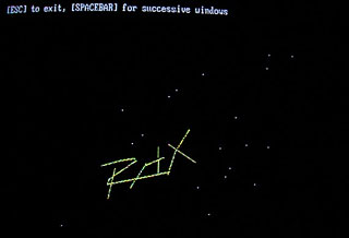
The sparse sequence below is built directly from the seven 640x350 DOSBox-X frames. It is not a fast motion clip; it is a compact view of the Space-key state changes where the clipped 3D line/window setup is the behavior being studied.

| Timestamp | Screen state |
|---|---|
00:04.000 |
First EGA dithered window, small rotating line/point state in the upper-left clipped viewport. |
00:08.000 |
Successive window state after a Space press, with a different projected line angle. |
00:12.000 |
The clipped black viewport is retained while the dithered background remains planar. |
00:16.000 |
A denser accumulated line state, close to the public Pouet screenshot's small Rax look. |
00:20.000 |
Another random/clipped window state with a blue line segment. |
00:24.000 |
Near-vertical white projected line state. |
00:28.000 |
Yellow projected line state before the scripted exit. |
The 00:32.000 exit frame was excluded because it displays the old postal
contact text.
Runtime-To-Code Concordance
The runtime GIF and stills are direct DOSBox-X frame evidence. They were not cropped, padded, resized, or rebuilt through a browser/lightbox path; the useful mapping is from the visible EGA frames back to the executable's graphics and math routines.
| Runtime evidence | Code anchor | What it explains |
|---|---|---|
| The 640x350 EGA capture size and 16-color dithered field | main at 0x0FFF, C interrupt wrapper 0x1828, register block DS:0D90, INT 10h / AX=0010h |
The frame dimensions come from BIOS EGA mode 10h. The mode set is hidden behind Microsoft C's generic interrupt wrapper, but it still loads AX=0010h before entering the demo loop. |
| The sequence changes after each scripted Space press | Demo loop 0x086B, BIOS keyboard helpers 0x15BF and 0x15D7, Space branch around 0x0986 |
Space is not a loader or part switch. It randomizes/recenters the active clipping window and lets the same renderer produce another small projected-line state. |
The optional O/o display-page behavior, even though it is not emphasized in the published GIF |
Key comparisons around 0x0966..0x0970, page-offset helper 0x15A3, cs:[105c] |
The program can flip its internal EGA base offset between 0x0000 and 0x8000, so address generation in the span writer has a real page component rather than a cosmetic variable. |
The rotating projected line and point positions at 00:04 through 00:28 |
Sine table DS:0044 / load offset 0x1D74, trig setup 0x03B7, cached coefficients DS:0E6C..0E76, transform 0x046E, projection 0x05F0 |
The visible movement is fixed-point 3D math. Angles use 1440 steps per turn, cosine is read as sine plus 360 steps, and projected coordinates are produced by integer multiply/divide helpers rather than FPU code. |
| The compact black/clipped drawing windows in the contact sheet | Window/span wrapper 0x001C, vertical wrapper 0x009D, general line routine 0x0113, horizontal clipper 0x13E7 |
The small viewports are software clipping regions. Lines are reduced to clipped horizontal/vertical spans before the low-level EGA writer touches memory. |
| The ordered 4096-color-looking texture behind the line states | Dither setup 0x10EE, dither table CS:106E, plane-mask coalescing 0x1210..0x1298 |
The "4096 colors" claim is an EGA ordered-dither trick. Four 16-bit pattern planes are prepared and duplicate plane passes are merged so the background is dense without requiring per-pixel BIOS plotting. |
| The crisp one-byte edges and wider filled runs | Low-level mask helper 0x12A1, word middle-span writer 0x12B6, byte/edge writer 0x134F, EGA ports 03CEh and 03C4h |
The program writes directly to planar EGA memory. It programs the Graphics Controller bit mask and Sequencer map mask, then uses byte edge masks and word middle fills for efficient spans. |
| The sparse GIF's successive line colors and redraws | Color/pattern wrapper 0x1524, point update/draw path 0x0B27..0x0C10, LCG 0x18BA |
The random-looking sequence is deterministic runtime state: moving point records are updated, projected, erased/redrawn with selected dither/color patterns, and respawned by the 32-bit LCG when they leave bounds. |
This is why the article treats the GIF as state evidence instead of as a normal motion clip. The interesting behavior is not high frame-rate animation; it is the combination of Space-triggered window selection, fixed-point projection, and span-based EGA planar drawing.
Archive Contents
Examined archive:
e95ca9340709a36200cf719c0873b887b103cfece709b14cba97110ae4ee3934 rax.zip
Extracted files:
659138c143e8391079e9a3d3b899068518b80a040e423feb5c29ba282aba49ec  rax.doc
8de56def30c2bc35a725885e0eb2a85d9e2169bef7d8af9704cee3752807c30c  rax.exe
The documentation describes the program as a "3 Dimensional EGA Demonstration" using 4096-color dithering on an Enhanced Graphics Adapter. It also states that the code uses no floating point arithmetic, so an 8087-style coprocessor has no effect on speed. That matches the executable: the interesting math is all integer multiply, divide, and shift code, with Microsoft C runtime support around it.
MZ Layout And C Runtime
rax.exe is a normal DOS MZ executable:
file size              11456 bytes
MZ header size          512 bytes
load image size       10944 bytes
entry point          CS:IP = 0000:177E
initial stack        SS:SP = 02BB:0800
relocation entries       3
minimum extra alloc    143 paragraphs
The entry point is Microsoft C startup code. It checks DOS version, adjusts
memory allocation, installs C runtime handlers, then calls the user main at
0x0FFF:
177e: mov  ah,30h
1780: int  21h              ; DOS version
...
17a6: cli
17a7: mov  ss,di            ; DI = 01D3h, runtime data/stack paragraph
17a9: add  sp,0e7eh
17ad: sti
...
17f8: push ss
17f9: pop  ds               ; DS = SS for C data references
...
1813: call 0fffh            ; user main
That DS = SS = load_segment + 01D3h detail matters. If the binary is treated
as a flat .COM-like image, the data tables appear to point into code. With the
correct data segment, the sine table and object data line up cleanly.
Main Function
The high-level main is small:
0fff: push bp
1000: mov  bp,sp
1008: mov  word [0d90h],0010h
100e: mov  ax,0d90h
1011: push ax               ; output register block
1012: push ax               ; input register block
1013: mov  ax,0010h
1016: push ax               ; interrupt 10h
1017: call 1828h            ; generic interrupt wrapper
101d: call 086bh            ; demo loop
1020: mov  word [0d90h],0003h
1026: mov  ax,0d90h
102b: mov  ax,0010h
102f: call 1828h            ; restore text mode 03h
1035: call 173dh            ; final text/copyright message
The register block at DS:0D90 starts with the requested AX value. So the
first BIOS call is INT 10h / AX=0010h, which is EGA 640x350 16-color mode.
The final BIOS call is INT 10h / AX=0003h, restoring text mode.
The interrupt wrapper at 0x1828 constructs a tiny stack-local int n; retf
stub and loads/stores a C register structure around it. That is why the mode
set is not visible as the usual hand-written:
mov ax,0010h
int 10h
It is still exactly that operation after the wrapper has loaded the register block.
Keyboard Flow
The keyboard helpers are BIOS INT 16h wrappers:
15bf: mov ax,0100h
15c5: int 16h               ; check for key, ZF set if none
...
15d7: call 15bfh
15e6: int 16h               ; read key
The animation loop handles:
095e: cmp ax,001bh          ; Esc
0963: jmp exit
0966: cmp ax,006fh          ; 'o'
096b: cmp ax,004fh          ; 'O'
0970: xor byte [bp-3ah],01h ; page/offset toggle
...
0986: cmp word [bp-30h],0020h ; Space
098f: randomize next window
The O/o path calls a BIOS display-page wrapper and also changes an internal
EGA page offset between 0x0000 and 0x8000:
15a3: cmp byte [bp+4],00h
15ae: mov ax,8000h
15b7: mov cs:[105ch],ax     ; base offset used by EGA address calculations
Space does not load another part. It picks a new clipping/window rectangle and recenters the local coordinate offset used by the line routines.
Fixed Point Tables
The angle domain is 0x05A0 units, or 1440 steps per full turn. The sine table
is at DS:0044, which maps to file/load-image offset 0x1D74 after the C
runtime data-segment shift:
table entries: 1440 signed words
minimum:       -32768
maximum:        32767
first entries:  0, 142, 285, 428, 571, 714, 857, 1000
quarter turn:   table[360]  = 32767
half turn:      table[720]  = 0
three-quarter:  table[1080] = -32768
The trigonometry setup routine is at 0x03B7:
03bf: add word [bp+4],05a0h ; normalize negative angle
03f8: mov ax,[bp+4]
03fc: mov cx,05a0h
03ff: idiv cx
0403: shl bx,1
0405: mov ax,[bx+0044h]     ; DS sine table
0409: mov [0e6ch],ax
040c: mov ax,[bp+4]
040f: add ax,0168h          ; +360 steps = cosine
0413: idiv cx
0419: mov ax,[bx+0044h]
041d: mov [0e72h],ax
The same pattern repeats for the other two input angles. The routine caches six
rotation coefficients at DS:0E6C..0E76. All later geometry uses those cached
fixed-point values.
Integer Multiply And Divide
The documentation's "no floating point" claim is accurate. Two runtime helpers carry the projection math:
1ced: mov  di,[bp+6]
1cf4: mov  ax,[bp+0ah]
1cff: je   simple
1d01: mul  cx
1d03: mov  di,ax
1d05: mov  ax,bx
1d07: mul  word [bp+6]
1d0a: add  di,ax
1d0c: mov  ax,bx
1d0e: mul  cx
1d10: add  dx,di
1d16: ret  8                ; unsigned 32-bit product-ish helper
0x1C4A is the signed division counterpart. It normalizes signs, handles a
zero high word as a fast case, shifts the divisor down until it fits the
hardware DIV, then corrects the quotient by one if the product overshot:
1c50: xor di,di             ; sign accumulator
1c55: or  ax,ax
1c57: jge numerator_positive
1c59: not di
1c5e: neg ax
1c60: neg dx
...
1ca9: shr bx,1
1cab: rcr cx,1
1cad: shr dx,1
1caf: rcr ax,1              ; scale down to fit 16-bit DIV
...
1cb5: div cx
...
1cd2: sub si,1              ; quotient correction
...
1cdd: neg dx
1cdf: neg ax
1ce1: sbb dx,0              ; reapply sign
This is exactly the kind of hand-support code a 1987 C program needed for smooth 3D-ish integer arithmetic on 286/386-era machines.
Rotation And Projection
The point transform routines are mostly C compiler output around those integer
helpers. The shorter routine at 0x046E takes pointers to x, y, and z,
applies cached sine/cosine terms, and writes the transformed coordinates back:
046e: push bp
0471: mov  ax,000ch
0474: call 1768h            ; stack check
0479: mov  ax,8000h         ; fixed-point scale
0480: mov  ax,[0e6eh]       ; cached coefficient
0486: mov  bx,[bp+8]        ; z pointer
0489: mov  ax,[bx]
048e: call 1cedh            ; coefficient * coordinate
...
04b0: call 1c4ah            ; divide by 0x8000
...
056f: mov  bx,[bp+8]
0572: mov  [bx],ax          ; store transformed z
...
05aa: mov  bx,[bp+4]
05ad: mov  [bx],ax          ; store transformed x
05e5: mov  bx,[bp+6]
05e8: mov  [bx],ax          ; store transformed y
The longer routine at 0x0682 is the same idea with extra parameters. It is
used for the active polyline object path where camera/object offsets change
between passes.
Perspective projection is handled by 0x05F0. It clamps z to at least one,
then uses shifted z as the divisor:
05f8: mov  bx,[bp+8]        ; z pointer
05fb: mov  ax,[bp+0eh]
05fe: add  [bx],ax          ; z += offset
0603: cmp  word [bx],0
0608: mov  word [bx],1      ; avoid divide by zero/negative
060f: mov  ax,[bx]
0612: mov  cl,06h
0614: call 1d19h            ; z <<= 6
...
062d: call 1d19h            ; numerator <<= 15
0632: call 1c4ah            ; projected x
...
0667: call 1cedh
066c: call 1c4ah
066f: call 1d19h
0676: call 1c4ah            ; projected y
The projection is therefore not using BIOS graphics primitives or floating point. It is signed fixed-point perspective math, with explicit integer multiply/divide support.
EGA Dither Setup
The most demo-specific routine is the color/pattern setup at 0x10EE. The
wrapper at 0x1524 passes three values into it:
1527: mov ax,[bp+4]
152a: mov bx,[bp+6]
152d: mov ah,bl
152f: mov bx,[bp+8]
1534: call 10eeh
0x10EE indexes a code-segment dither table at CS:106E. The table maps a
small color/intensity value to four 16-bit patterns. The routine loads pattern
words for multiple components, ORs overlapping pattern planes together, and
prepares per-plane map masks:
10ee: mov cl,03h
10f0: xor bh,bh
10f2: shl bl,cl             ; 8 bytes per table entry
10f4: shl ax,cl             ; AL/AH become table offsets too
10f6: mov cx,cs:[bx+106eh]
10fb: mov cs:[1044h],cx
1103: mov dx,cs:[bx+106eh]
1108: mov cs:[1046h],dx
1110: mov di,cs:[bx+106eh]
1115: mov cs:[1048h],di
111d: mov si,cs:[bx+106eh]
1122: mov cs:[104ah],si
...
119d: mov cs:[1054h],cx     ; merged pattern plane
11a2: mov cs:[1056h],dx
11a7: mov cs:[1058h],di
11ac: mov byte cs:[105eh],04h ; plane masks: 4,2,1,8
11c4: mov byte cs:[1062h],02h
11dc: mov byte cs:[1066h],01h
11f4: mov byte cs:[106ah],08h
After loading the pattern words, 0x1210..0x1298 compares the four pattern
sets. If two sets are identical, it ORs their EGA plane masks together and
zeros the duplicate pass:
1224: cmp ax,cx
1228: or  byte cs:[di+105eh],02h
122e: mov byte cs:[di+1062h],00h
...
125c: cmp cx,dx
1260: or  byte cs:[di+1062h],01h
1266: mov byte cs:[di+1066h],00h
That is an early and very practical EGA optimization. Instead of writing the same byte pattern separately to several planes, it merges the plane masks and does fewer memory passes.
EGA Pixel And Span Writers
Rax writes directly to EGA planar memory. 0x12A1 is the low-level register
helper:
12a1: mov dx,03ceh
12a4: mov al,08h
12a6: out dx,al             ; Graphics Controller index 8: bit mask
12a7: inc dx
12a8: mov al,bl
12aa: out dx,al
12ab: mov dx,03c4h
12ae: mov al,02h
12b0: out dx,al             ; Sequencer index 2: map mask
12b1: inc dx
12b2: mov al,bh
12b4: out dx,al
The single-byte/edge writer at 0x134F uses AH as the bit mask and SI as
the dither row selector. It selects a plane mask, reads the latch byte, writes
one byte, then repeats for nonzero merged masks:
1353: mov dx,03ceh
1356: mov al,08h
1358: out dx,al
135a: mov al,ah
135c: out dx,al             ; edge bit mask
135d: mov dx,03c4h
1360: mov al,02h
1362: out dx,al
1364: mov al,cs:[di+105eh]  ; first plane mask
1369: out dx,al
136a: mov ax,cs:[si+103ch]  ; byte pattern
136f: mov ah,[bx]           ; load EGA latches
1371: mov [bx],al           ; write selected planes
...
13bb: mov bx,ffffh
13be: call 12a1h            ; restore full masks
The middle-span writer at 0x12B6 works in words, so long horizontal fills are
not forced through byte-at-a-time edge code:
12ba: shl si,1
12c3: mov al,0ffh
12c5: out dx,al             ; full 8-pixel mask
12cd: mov al,cs:[di+105eh]
12d2: out dx,al             ; plane mask
12d3: mov ax,cs:[si+103ch]  ; pattern word
12d8: mov dx,[bx]           ; latch
12da: mov [bx],ax
12dc: add bx,2
12df: loop 12d8h
...
1348: mov bx,ffffh
134b: call 12a1h            ; reset bit/map masks
This explains the screen look: the background is not a 4096-color DAC trick. It is a dense ordered dither written into four EGA planes. Different 2D patterns across the 16 hardware colors simulate many more apparent shades.
Horizontal Line Clipper
The horizontal span routine is at 0x13E7. It rejects off-screen y, stores
the original endpoints, converts pixel x values into byte addresses, and
chooses edge masks from two small code-segment mask tables:
13e7: cmp dx,0
13ec: cmp dx,015eh
13f2: ret                   ; y outside 0..349
13f3: mov cs:[13d3h],ax     ; x1
13f7: mov cs:[13d5h],bx     ; x2
13fc: mov cs:[13d7h],dx     ; y
1401: mov cl,03h
1403: shr ax,cl             ; x1 byte
1409: shr bx,cl             ; x2 byte
1418: mov bx,dx
141a: shl dx,1
141c: shl dx,1
141e: add dx,bx             ; y * 5
1421: shl dx,cl             ; y * 80
1423: add dx,ax             ; + x byte
1425: add dx,cs:[105ch]     ; page offset
If the line is a one-byte span, it ANDs the left-edge and right-edge masks together and calls the byte writer once:
143a: cmp word cs:[13e5h],1
1442: mov si,ax             ; dither row selector
144d: mov ah,cs:[bx+13c2h]  ; left mask
145b: and ah,cs:[bx+13cbh]  ; right mask
1462: call 134fh
For longer spans it writes a left edge, an even number of middle bytes through the word writer, then a right edge:
1471: mov si,ax
1473: mov ah,cs:[bx+13c2h]
147a: call 134fh            ; left edge
...
14da: shr cx,1
14dc: mov si,cs:[13dfh]
14e1: call 12b6h            ; middle words
...
1516: mov ah,cs:[bx+13cbh]
1520: call 134fh            ; right edge
This is the central EGA inner loop. It avoids per-pixel plotting for the dithered background and line fills, while still honoring exact bit masks at the byte boundaries.
Higher-Level Line Drawing
The wrapper at 0x001C clips horizontal spans to the active window and then
calls the EGA span routine:
0026: mov si,[bp+4]         ; x1
0029: mov di,[bp+6]         ; x2
002c: add si,[003eh]        ; window x offset
0030: add di,[003eh]
0034: mov ax,[0040h]        ; window y offset
0037: add [bp+8],ax
003d: cmp [bp+8],ax         ; y clip against [0036h,0038h)
...
008c: push [bp+8]
008f: push di
0090: push si
0091: call 155bh            ; DS=A000h, then 13E7
The vertical-line wrapper at 0x009D simply calls the horizontal span helper
once per row with equal endpoints:
00fb: push si
00fc: inc si
00fd: push [bp+4]
0100: push [bp+4]
0103: call 155bh
0109: cmp si,di
010b: jle 00fbh
The general line routine at 0x0113 handles horizontal and vertical specials,
then uses a fixed-point Bresenham-like path. It repeatedly calls the horizontal
or vertical helpers after each accumulated step:
011c: mov ax,[bp+0ah]
011f: cmp [bp+6],ax
0124: call 001ch            ; horizontal special
...
013e: call 009dh            ; vertical special
...
01af: call 1c4ah            ; slope ratio
...
01ed: dec word [bp+8]
01f0: call 009dh            ; draw short vertical run
...
0307: push [bp+6]
0313: call 001ch            ; draw short horizontal run
Because the low-level writer is span-based, even the general line routine tends to reduce work into clipped horizontal/vertical runs instead of plotting every pixel through a BIOS call.
Animation Loop
The main demo loop starts at 0x086B. It initializes page/window state, angular
velocities, and 20 moving point records:
086b: push bp
086e: mov ax,0052h
0871: call 1768h            ; stack frame check
0876: mov word [bp-3ah],0   ; page toggle
0885: mov word [bp-0eh],0bb8h
0899: mov word [bp-22h],4
089e: mov word [bp-2ah],2
08a3: mov word [bp-32h],8
...
090c: call 18bah            ; random x
0911: sar ax,7
0913: sub ax,80h
091b: mov [bx+0da4h],ax
091f: call 18bah            ; random y
0924: sar ax,7
0926: sub ax,80h
092e: mov [bx+0dcch],ax
0932: call 18bah            ; random z
0937: sar ax,3
093e: mov [bx+0df4h],ax
0942: inc word [bp-40h]
0945: cmp word [bp-40h],14h ; 20 records
0949: jl  090ch
The random generator at 0x18BA is a 32-bit linear congruential generator:
18bd: mov ax,43fdh
18c0: mov dx,0003h
18c5: push [0c46h]
18c9: push [0c44h]
18cd: call 1cedh            ; state * 000343FDh
18d0: add ax,9ec3h
18d3: adc dx,0026h          ; + 0000269EC3h
18d6: mov [0c44h],ax
18d9: mov [0c46h],dx
18dd: mov ax,dx
18df: and ah,7fh
Each frame then:
- Checks the keyboard.
- Optionally picks a new clipped window on Space.
- Sets the current dither pattern/color through
0x1524. - Updates and projects 20 moving point records.
- Draws old and new point/line states through the span helpers.
- Advances the rotation angles modulo
0x05A0.
The point update path is visible at 0x0B27:
0b27: mov si,[bp-40h]
0b2c: mov ax,[bp-26h]
0b2f: sub [si+0df4h],ax     ; z -= velocity
0b33: cmp word [si+0df4h],64h
0b3a: cmp word [si+0e1ch],0fec0h
0b42: cmp word [si+0e1ch],0140h
0b4a: cmp word [si+0e44h],0ff51h
0b52: cmp word [si+0e44h],00afh
0b5a: call 18bah            ; respawn if outside bounds
...
0ba2: call 046eh            ; rotate/update point
0bd3: call 05f0h            ; project point
0bde: call 1524h            ; select dither/color 0
0bf5: call 001ch            ; erase/draw old position
0c01: call 1524h            ; select color 15
0c10: call 001ch            ; draw new position
The active polyline path at 0x0D7E..0x0F83 uses the signed coordinate list at
DS:0B84. The first active list begins:
(-370, 170), (-270, -50), 0x8000, 0x8000
That looks tiny compared with later demo object formats, but it is enough for the rotating clipped line/window behavior. The richer visual comes from the EGA dither field, repeated clipped redraws, moving point records, and the successive window logic rather than from a large stored bitmap or polygon mesh.
Why It Matters
Rax is early enough that it does not look like the 1991-1993 VGA demo style.
There is no Sound Blaster driver, no packed part loader, no chunky framebuffer,
and no DAC palette cycling. The interesting work is instead:
- C 4.0 real-mode startup wrapped around hand-relevant graphics/math kernels.
- Mode
10hEGA planar output at 640x350. - Ordered dithering to simulate a larger 4096-color space on 16-color EGA.
- Direct
03CEh/03C4hbit-mask and map-mask programming. - Span-based EGA writers with byte-edge masks and word middle fills.
- Signed fixed-point rotation/projection with no floating point.
- Window clipping and successive Space-triggered redraw states.
That combination is exactly what makes it a useful 1987 baseline: it is not a modern PC demo yet, but it already has the core habits that later PC demos kept refining - direct hardware writes, fixed-point transforms, precomputed tables, and custom inner loops designed around the display adapter's real memory model.