Analysis model: gpt-5.5 xhigh
GR8 by Future Crew - Technical Dissection
Scope
This is a code-level pass over GR8 by Future Crew, an early MS-DOS PC
production distributed as one MZ executable plus six GR8.FC* resource files.
It sits right at the point where PC demos were moving from text screens and
simple intros into custom VGA/EGA graphics code, but before Future Crew's later
all-assembler engines.
Public references:
- Pouet production: https://www.pouet.net/prod.php?which=2998
- Demozoo production: https://demozoo.org/productions/99537/
- Scene.org archive: https://files.scene.org/view/demos/groups/future_crew/intros/gr8.zip
- Hornet 1989 mirror index: https://files.scene.org/view/mirrors/hornet/demos/1989/00_index.txt
The dating is slightly messy. Demozoo lists 12 July 1989, and Hornet carries
gr8.zip in its 1989 demo index. Pouet lists January 1990, and the files in
the Scene.org archive are stamped late December 1989 and early January 1990.
For this series I would record the release year as 1989/1990, with the
important point being that it is a very early Future Crew PC release.
Historical scrolltext and contact details embedded in the executable are not reproduced here. The text is useful for confirming intent and controls, but the analysis below is based on the executable, resource files, and restored code layout.
Examined Files
The archive used for this pass was:
eec74172aa20530d0387541f45f15c9a057db241bfb6eaa8bef09392c41be4ab gr8.zip
It contains:
| File | Size | SHA-256 | Role |
|---|---|---|---|
GR8.EXE |
38,864 | faf44d9a9ac1f49f5af0aab9eb3c8744f8fccba970a6ccb5e010f8403b44b4ad |
packed real-mode MZ executable |
GR8.FC1 |
1,250 | bc38cf6e76caa8ecd9d17ad5e65f1045a32b99579514c92af6ab39acf6807e9b |
vector glyph/object topology |
GR8.FC2 |
1,444 | 60eed61e6af49787e0dbf7f96c6883184bb315417cba12675ead98ac8c1ab842 |
360-entry sine/cosine table |
GR8.FC3 |
3,607 | c202b6efbacac8a3ef8f4f3bf062b9ee739d44c58b88816f36a08a9cdf02b614 |
packed planar picture/frame data |
GR8.FC4 |
3,626 | b3e0af95485b8f4ff4941d0b2befc1394563bcc30d668057ebe60d3ec8d813cd |
packed planar picture/frame data |
GR8.FC5 |
3,692 | 29625a69c9437eecda5d8d8903dc8be4876c2666866d2534db2b48914b64a0eb |
packed planar picture/frame data |
GR8.FC6 |
3,517 | 00096c36f8b9b6ee372a0c876b93b86bddfc1ae7f7b53881c873601a4c47e757 |
packed planar picture/frame data |
scene.org |
2,033 | 7cf81d4c83d4c54346d7f2f564f0c5b24b2f23e3b7360400c4b94515fb704121 |
archive note |
The four large picture resources all start with runs like 01 FD 00, which
matches the simple RLE command format recovered from the loader: command byte
01, count FDh, value 00.
Runtime Capture
A DOSBox-X 2026.01.02 capture on 19 June 2026 used the public Scene.org
gr8.zip archive and the original packed GR8.EXE. The run used SDL dummy
video/audio, machine=svga_s3, normal CPU core, cycles=30000, xms=true,
ems=false, nosound=true, and no Sound Blaster device. Timing zero is the
start of dx-capture /v GR8.EXE.
The capture is a 44.273933-second MPEG-TS/H.264 stream at 640x400. ffmpeg
reported one corrupt decoded frame around an early mode transition; the frames
below were taken from a sequential 1 fps decode and checked visually. The run
stays in the default visible effect: the Future Crew logo, sparse starfield,
and a large rotating red text ring. No input was sent, so the +/- text-speed
control remained at the default speed and ESC was not used.
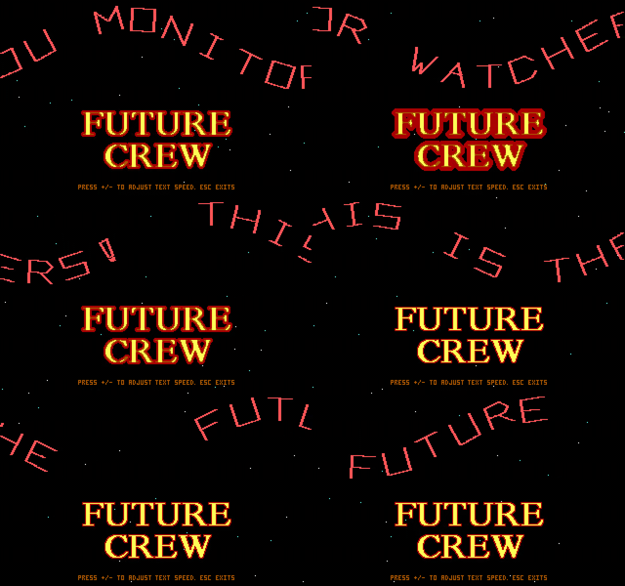
The short clip below is sliced directly from the DOSBox-X capture at native 640x400. It is included because the red text ring is the clearest viewer-facing result of the vector glyph/object transform and redraw path discussed later in the article.
| Timestamp | Frame | Runtime context |
|---|---|---|
00:00.000 |
 |
The first stable screen establishes the mode: Future Crew logo over black, sparse star dots, and the keyboard hint line at the bottom. |
00:02.000 |
 |
The large red text ring has entered from the upper edge. This is the viewer-facing result of the vector glyph/object transform and edge drawing code described below. |
00:05.000 |
 |
The ring continues across the starfield while the logo remains stable. The effect is not a pre-rendered movie; it is redrawn over the same planar mode state. |
00:10.000 |
 |
The rotating glyph path is now closer to the logo area, showing how the top text and central picture share one EGA/VGA mode-0Dh presentation. |
00:16.000 |
 |
A greeting fragment is visible in the ring. This anchors the scroller/glyph data path without reproducing any historical private contact material. |
00:24.000 |
 |
The same effect has advanced to another public text fragment. The background stars continue to update while the central logo stays in place. |
00:32.000 |
 |
A later frame shows another ring position and text fragment. The useful technical point is the sustained redraw loop: starfield, glyph transform, and page/state updates rather than a multi-scene part chain. |
Runtime-To-Code Concordance
The GIF and stills above all show the same default no-input loop. That matters:
the frames are not separate pictures or a pre-rendered animation sequence. They
are repeated executions of the loader/frame loop at 0097:0002, with the
custom planar drawing routines in segment 0000 and the object/star routines in
segment 0097.
- The stable Future Crew logo at
00:00.000comes from theGR8.FC3toGR8.FC6planar resources. Those are decoded as 8,000-byte plane blocks by the RLE loader and then restored each frame through the0000:0404planar copy helper. - The red ring entering at
00:02.000, crossing the logo at00:05.000, and sitting over the logo at00:10.000is the ten-slot text path. The frame code around raw offset0x121acomputes each slot's path position, then calls0097:0f56to transform theGR8.FC1vector glyph points with theGR8.FC2sine/cosine table. - The thick red strokes in the GIF are not bitmap-font pixels. After
0097:0f56transforms the points, each stored edge calls the line drawer at0000:024f, which steps vertically and emits three-pixel strokes through the0000:03abplanar plotter. - The sparse white dots that remain visible around the logo are the starfield
routine at
0097:1174. It keeps 24 persistent fixed-point stars, respawns them at the right edge, and only plots a star when the destination pixel is black, which is why the dots do not punch through the red text or logo. - The public fragments visible around
00:16.000,00:24.000, and00:32.000are scrolltext bytes being converted into object IDs by the text interpreter. The writeup intentionally describes the mechanism without reproducing the historical contact text. - The smoothness of the GIF is bounded by two timing layers: the high-rate PIT
hook at
0000:0604/0000:0685and the visible-page handoff through the retrace waits at0000:043eand0000:044d.
So the runtime evidence is a direct witness for the core code structure: resource-plane restore, vector glyph transform, custom planar line plotting, fixed-point stars, keyboard-controlled speed, and vblank page flipping all operate together inside one sustained Future Crew frame loop.
Packed Executable
The distributed executable is packed:
packed file size:       38,864 bytes
MZ header size:            512 bytes
declared load image:    38,352 bytes
entry point:           092a:0010
relocations:                 0
The entry stub is the same family of early DOS EXE compressor used by several small productions of the period. It copies the packed stream upward with the direction flag set, then interprets a bytecode with two useful operations:
command B0/B1: read one byte and repeat it CX times with REP STOSB
command B2/B3: copy CX literal bytes with REP MOVSB
low command bit set: this is the final block
After the last block, the stub walks a relocation table, adjusts segment references, restores the intended stack, and transfers control to the expanded program. If the command byte is not one of the known forms, it exits through DOS after printing a short corrupt-file message.
Restoring the file with UNP produced:
restored file size:     40,528 bytes
header size:               992 bytes
load image:             39,536 bytes
relocations:               239
entry point:           01c8:0010
SHA-256: c302e355fd4f9d0f71445a86d416348560be32a69c832a5873e17e85c6e7c85b
The restored load image starts with a short joke string intended for people looking at the EXE as text. The actual entry point is Microsoft C startup code, not the demo's main routine.
Code Layout
This binary is a mix of three things:
- Microsoft C 1989 startup/runtime.
- Microsoft graphics and C library routines.
- Future Crew's own demo code, including custom planar VGA/EGA helpers.
The important addresses in the restored load image are:
| Logical address | Raw load-image offset | Role |
|---|---|---|
01c8:0010 |
0x1c90 |
Microsoft C startup entry |
0097:0002 |
0x0972 |
demo main |
0000:024f |
0x024f |
thick line/vector stroke drawer |
0000:0344 |
0x0344 |
far-call pixel wrapper |
0000:0357 |
0x0357 |
single planar pixel plot inner loop |
0000:03ab |
0x03ab |
three-pixel-wide plot used by vector lines |
0000:0404 |
0x0404 |
8,000-byte planar block copy |
0000:043e |
0x043e |
wait until vertical retrace is active |
0000:044d |
0x044d |
wait until vertical retrace is inactive |
0000:0604 |
0x0604 |
timer hook/PIT setup |
0000:0685 |
0x0685 |
IRQ0 handler |
0097:0f56 |
0x18c6 |
vector glyph/object transform and edge drawer |
0097:1174 |
0x1ae4 |
starfield update and plotter |
0097:12ae |
0x1c1e |
sequencer map-mask writer |
0097:12d2 |
0x1c42 |
keyboard read normalizer |
The C startup checks DOS version, resizes the memory block, clears BSS, builds
the argument/environment state, and then far-calls 0097:0002. That startup
and the later 0406:* graphics calls should not be confused with the demo's
own effect loops. The demo uses the library for setup, pages, pixel reads,
color state, file I/O, and buffered input; the distinctive rendering loops are
the routines in segments 0000 and 0097.
Video Mode And Page State
The first real action in main is:
push 000Dh
lcall 0406:0013
That is a Microsoft graphics-library call to set 320x200 16-color planar
graphics mode, equivalent to BIOS mode 0Dh. In this mode each scanline is 40
bytes per plane: 320 pixels / 8 pixels per byte.
Immediately after setting the mode, the demo builds its own scanline table for the custom pixel routines:
for y = 0..199:
    row_offset[y] = y * 40
The disassembly is compact:
DI = 0
loop:
    AX = 0028h * DI
    ES:[0076h + DI*2] = AX
    DI++
    if DI < 200: loop
That row table is not a Microsoft graphics-library table. It is used directly
by the hand-written pixel and line routines in segment 0000.
The active VGA memory segment is kept in CS:0074. Function 0000:0470
updates that word:
CS:0074 = requested_vram_segment
The main loop calls it with one of two values from a page table, then calls the graphics library's page-select routine. The result is a classic draw-page / visible-page arrangement: draw into the hidden page, wait for vertical retrace, make it visible, then flip the page index.
Single-Pixel Planar Inner Loop
The lowest useful graphics primitive is 0000:0357. The far wrapper at
0000:0344 loads x, y, and color, then calls this near routine.
The algorithm is:
plot_pixel(x, y, color):
    if x < 0 or x > 319: return
    if y < 0 or y > 199: return

    bit = 0x80 >> (x & 7)

    GC[8] = bit              ; bit mask register
    GC[5] = write mode 2     ; CPU low nibble selects color planes

    offset = row_offset[y] + (x >> 3)
    ES = current_vram_segment

    dummy = ES:[offset]      ; load VGA/EGA latches
    ES:[offset] = color      ; write one masked pixel
The relevant instruction sequence is:
AX = x
AX = AX & 0007h
CL = AL
AL = 80h
AL >>= CL
AH = AL
AL = 08h
DX = 03CEh
OUT DX, AX          ; graphics-controller index 8, bit mask = 80>>(x&7)

AX = 0205h
DX = 03CEh
OUT DX, AX          ; graphics-controller index 5, write mode 2

BX = y * 2
AX = CS:[0076h + BX]
BX = x >> 3
BX += AX
ES = CS:[0074]
AL = ES:[BX]        ; latch read
ES:[BX] = DL        ; DL is color
This is exactly the normal EGA/VGA single-pixel trick. In write mode 2, the CPU byte is interpreted as a 4-bit color value. The bit-mask register restricts the write to one bit position inside the addressed byte. The dummy read is required because planar writes combine the CPU data with the card's internal latches.
The three-pixel routine at 0000:03ab repeats the same inner sequence three
times while incrementing x. This gives the vector letters thicker strokes:
for n = 0..2:
    plot one planar pixel at x+n, y
It is simple rather than fast: each of the three pixels reprograms the VGA graphics-controller bit mask. For this demo, that is acceptable because the vector objects are small.
Thick Vector Line Drawer
The line routine starts at 0000:024f. It is the real inner loop behind the
rotating vector glyphs.
The caller pushes:
color
y2
x2
y1
x1
lcall 0000:024f
The routine first adds 100 to all four coordinates:
x1 += 100
y1 += 100
x2 += 100
y2 += 100
That lets the glyph data use signed, centered coordinates while the low-level line loop mostly works with positive values. Just before plotting, it subtracts 100 again for the pixel call.
It then makes the line vertical-major by sorting the endpoints by y:
if y1 > y2:
    swap(x1, x2)
    swap(y1, y2)
The helper at 0000:02e9 computes the slope state. It handles the sign of the
x movement, computes the whole-pixel step, and computes a fractional residue
using integer division:
dx = abs(x2 - x1)
dy = y2 - y1 + 1

whole_step = dx / dy
remainder  = dx % dy
fraction_step = floor(65535 / dy) * remainder
sign = +1 or -1
The main line loop is then:
x = x1
frac = 0

for y = y1..y2:
    plot_3_pixels(x - 100, y - 100, color)

    x += sign * whole_step
    frac += fraction_step
    if carry_from_frac_add:
        x += sign
That is not a general fast Bresenham over arbitrary octants; it is a
vertical-major stroke drawer tuned for these glyph outlines. The thick plotter
at 0000:03ab supplies the visual weight by drawing three adjacent pixels per
step.
GR8.FC1: Vector Glyph/Object Format
GR8.FC1 starts with:
47 52 38 1A
That is the ASCII signature GR8 plus DOS text EOF byte 1Ah. After those
four bytes, the file is a compact 64-object vector dataset. The parser in
main skips the header and then runs this shape:
for object = 0..63:
    point_count[object] = read_byte()

    for point = 0..point_count[object]-1:
        y_table[object][point] = read_byte() - 15
        x_table[object][point] = read_byte() - 15

    edge_count[object] = read_byte()

    for edge = 0..edge_count[object]-1:
        edge_table[object][edge].a = read_byte()
        edge_table[object][edge].b = read_byte()
The storage in BSS uses word entries even though the file stores bytes:
| Table | Offset | Shape |
|---|---|---|
| point counts | DS:2182 |
64 words |
| edge counts | DS:2100 |
64 words |
| coordinate A | DS:2cf6 |
64 objects * 16 words |
| coordinate B | DS:3516 |
64 objects * 16 words |
| edge pairs | DS:24d6 |
64 objects * 8 pairs, two words per pair |
The per-object coordinate stride is 32 bytes, so a glyph can have up to 16
points. The edge stride is also 32 bytes, so a glyph can have up to 8 stored
edge pairs. The -15 bias is the important compression detail: most glyph
points are small positive bytes in the file, and the loader recenters them into
a roughly signed coordinate range.
After loading, main writes point_count[0] = 16. I would not treat that as
part of the file format. It is a runtime guard/initialization write for the
first object slot, done after the serialized FC1 data has already been parsed.
GR8.FC2: Sine And Cosine Table
GR8.FC2 also starts with GR8 1A, but its size gives away the format:
4-byte header + 360 * 4 bytes = 1,444 bytes
The parser reads 360 little-endian word pairs:
for angle = 0..359:
    sin_table[angle] = read_word_le()
    cos_table[angle] = read_word_le()
The first pair after the header is 0000h, 03E8h, meaning sin(0)=0 and
cos(0)=1000. The tables are scaled by 1000 and are used directly by the
vector object transform.
The first few bytes after the header look like this:
00 00 E8 03 11 00 E7 03 22 00 E7 03 34 00 E6 03
Interpreted as words:
0, 1000
17, 999
34, 999
52, 998
That is exactly a one-degree trigonometry table.
GR8.FC3 To GR8.FC6: Packed Planar Pictures
The four larger resource files are loaded after FC1 and FC2. The code opens
four filenames from a small table, then decodes each file into an 8,000-byte
planar block. The unpacker is extremely small:
while destination plane is not full:
    command = read_byte()

    if command == 1:
        count = read_byte()
        value = read_byte()
        repeat count times:
            *dst++ = value
    else:
        *dst++ = command

    if dst passed the current 8,000-byte plane:
        wrap dst back to the start
        select next VGA plane mask
This explains the leading pattern in the picture files:
01 FD 00 01 FD 00 01 FD 00 ...
Those are long zero runs. The plane select step calls 0097:12ae, which writes
sequencer register 2:
OUT 03C4h, 0002h     ; select sequencer map-mask index
OUT 03C5h, mask      ; write one of the plane masks
In other words, the pictures are not stored as chunky pixels. They are decoded as planar data, one VGA/EGA plane at a time, into 8 KB chunks that match a 320x200 16-color page: 40 bytes * 200 rows = 8,000 bytes per plane.
Text Slots And Scroll Interpreter
The executable embeds a long scrolltext at raw load-image offset 0x838f.
The text itself includes ordinary ASCII and inline control bytes. The main loop
does not draw a bitmap font. It turns characters into vector objects from
GR8.FC1.
There are ten active text/object slots. At initialization:
for slot = 0..9:
    slot_phase[slot] = slot * 35

for star = 0..23:
    star_speed[star] = 1
    star_x_fixed[star] = star * 4
    star_y_fixed[star] = 201
The 35 is not arbitrary. Ten slots spaced by 35 gives a 350-unit loop, and
the runtime wrap value is 015Eh (350). The slots are staggered along the
path, so the text objects move in a chain rather than all occupying one
position.
Each normal frame visits the ten slots:
for slot = 0..9:
    if slot_phase[slot] is ready relative to speed:
        code = scrolltext[scroll_index++]
        interpret code
The mapping is table/switch-like:
| Input byte | Effect |
|---|---|
| space | blank object |
| punctuation | fixed object IDs for punctuation glyphs |
| digits | object ID derived by arithmetic |
| letters | object ID derived by arithmetic |
| selected high bytes | fixed object IDs for special glyphs |
a |
start a long pause counter |
b / c |
ramp the spin/shape scale down or up |
d |
trigger a flying ten-object transition |
f / g |
force the spin/shape scale to 0 or 100 |
z |
reset the slot glyphs and restart the text pointer |
The visible controls confirmed by the embedded text and keyboard handler are:
ESC  exit
+    increase text/effect speed, capped at 32
-    decrease text/effect speed, floored at 0
The normal slot update decreases every slot phase by the current speed and wraps negative values by adding 350:
for slot = 0..9:
    slot_phase[slot] -= speed
    if slot_phase[slot] < 0:
        slot_phase[slot] += 350
That is the small timing loop behind the moving vector text.
Vector Glyph Transform
The glyph/object renderer is 0097:0f56, raw load-image offset 0x18c6.
Its inputs are:
object_id
center_a
center_b
angle
Before drawing, the angle is scaled by runtime variable DS:0690:
angle = angle * DS:0690 / 100
if angle < 0:
    angle += 360
That variable is controlled by the scroll interpreter. Some commands set it
directly to 0 or 100; other commands ramp it up or down by changing DS:068e.
When it is zero, the glyphs collapse into a non-rotated path. When it is 100,
the full sine/cosine table is used.
The point transform loop reads the point count from DS:2182[object], loads
the two coordinate tables from GR8.FC1, and writes transformed screen points
to temporary arrays at DS:3d36 and DS:3d58.
Using the names a = table_2cf6[object][point] and
b = table_3516[object][point], the exact recovered math is:
s = sin_table[angle]
c = cos_table[angle]

screen_x[point] = center_a + ( a*s + b*c) / 1000
screen_y[point] = center_b + (-b*s + a*c) / 1000
That is a 2D rotation-like matrix with the source axes arranged to match the
stored glyph coordinate convention. The important implementation detail is that
it uses 16-bit signed multiplies (IMUL) and signed division by 1000. There is
no floating point and no per-frame sine calculation.
After all points are transformed, the edge loop walks the edge-pair table:
for edge_index = 0; edge_index < edge_count[object] * 2; edge_index += 2:
    p0 = edge_table[object][edge_index + 0]
    p1 = edge_table[object][edge_index + 1]

    draw_line(
        screen_x[p0], screen_y[p0],
        screen_x[p1], screen_y[p1],
        color = 12
    )
That final call is the 0000:024f thick line routine described earlier.
Text Path And Per-Slot Drawing
The top-level frame code at raw offset 0x121a draws each slot on a trigonometric
path. For every visible slot it computes an angle:
path_angle = slot_phase[slot] + global_path_angle
if path_angle > 359:
    path_angle -= 360
Then it calls the vector renderer with:
object_id = slot_glyph[slot]
center_a  = slot_phase[slot] - 20
center_b  = 50 + path_table[path_angle] * spin_scale / 100
angle     = second_path_table[path_angle]
The two path tables are small word tables in the executable image. They are
not the GR8.FC2 transform tables, but they are used the same way: a
precomputed path value avoids doing expensive trigonometry during the frame.
The visual result is that the vector characters do not merely scroll in a
straight horizontal line. Each slot has a phase, the phase feeds a path, and
the glyph itself is transformed through the GR8.FC2 sine/cosine table.
Flying Ten-Object Transition
Scroll command d enters a separate transition path. The code snapshots the
ten current glyphs into three arrays:
fly_x[slot]     = slot_phase[slot] - 20
fly_y[slot]     = 50 + path_table[path_angle] * spin_scale / 100
fly_angle[slot] = second_path_table[path_angle]
Then a tight animation loop runs until every object has fallen below the active area:
while any slot is still visible:
    select draw page
    restore background block

    any_visible = false

    for slot = 0..9:
        if fly_y[slot] < 216:
            any_visible = true
            draw_glyph(slot_glyph[slot], fly_x[slot], fly_y[slot], fly_angle[slot])

            fly_x[slot] += (fly_angle[slot] % 5) - 2
            fly_y[slot] += 3
            fly_angle[slot] += 5

    draw_stars()
    wait for retrace and flip page
The horizontal drift uses only the remainder of the angle divided by 5. That is cheap, deterministic, and enough to make the objects spread while falling.
Starfield Inner Loop
The starfield is 0097:1174, raw offset 0x1ae4. It tracks 24 stars using
fixed-point coordinates scaled by 100.
The main loop is:
for star = 0..23:
    star_x_fixed[star] -= star_speed[star]

    x = star_x_fixed[star] / 100
    y = star_y_fixed[star] / 100

    if star_x_fixed[star] < 0:
        star_x_fixed[star] = 31900
        star_color[star] = color_table[rand() % 2]
        star_y_fixed[star] = (rand() % 200) * 100
        star_speed[star] = (rand() % 800) + 50

        x = star_x_fixed[star] / 100
        y = star_y_fixed[star] / 100

    if get_pixel(x, y) == 0:
        plot_pixel(x, y, star_color[star])
There are two details worth noticing.
First, the stars move leftward from x=319 to x=0. They are not generated as
random screen dots every frame; each has persistent fixed-point position and
speed.
Second, the code reads the destination pixel before plotting. If the pixel is already nonzero, the star is skipped. That prevents the starfield from punching through vector letters or foreground picture data.
Timer Hook
The timer setup at 0000:0604 hooks interrupt 8 and programs the PIT:
old_int8 = get_vector(08h)
set_vector(08h, 0000:0685)

OUT 43h, 36h
OUT 40h, low(174Eh)
OUT 40h, high(174Eh)
The divisor 174Eh is decimal 5966. With the PC PIT input clock around
1.19318 MHz, that is about 200 Hz.
The IRQ0 handler is small:
tick_wait_counter++
global_counter = min(global_counter + 1, 4D58h)
bios_tick_shadow++

pit_accumulator += 174Eh
if carry:
    jump old_int8
else:
    send PIC EOI
    iret
The accumulator preserves the original BIOS tick rate by chaining to the old handler only when enough high-frequency ticks have accumulated. Otherwise the demo acknowledges the PIC itself and returns quickly.
There is also a wait helper:
wait_ticks(n):
    while tick_wait_counter < n:
        spin
The visible frame pacing still relies heavily on VGA vertical-retrace waits, but the timer hook gives the program a consistent high-frequency timebase.
Keyboard Handling
The key read wrapper at 0097:12d2 normalizes BIOS keyboard results:
raw = bios_key_read()

if low_byte(raw) != 0:
    return low_byte(raw)
else:
    return 1000 + high_byte(raw)
The main loop only needs ordinary ASCII keys for its public controls:
if key == ESC:
    exit
elif key == '+':
    if speed < 32:
        speed++
elif key == '-':
    if speed > 0:
        speed--
The scroll interpreter handles most of the show control. The live keyboard input only changes text/effect speed or aborts.
Per-Frame Order
Once initialization is complete, the normal frame is approximately:
1. Set the custom pixel routines' VRAM segment for the hidden page.
2. Tell the Microsoft graphics library to use the same draw page.
3. Restore/copy the current 8,000-byte planar background block.
4. Update and draw the ten vector text/object slots.
5. Update scroll-control state such as pauses and spin-scale ramps.
6. Poll keyboard and adjust speed or exit.
7. Draw the 24-star field, skipping occupied pixels.
8. Wait outside retrace.
9. Tell the graphics library to show the page.
10. Wait for retrace.
11. XOR the page index with 1.
The copy in step 3 uses 0000:0404, which enables all VGA planes and copies
8,000 bytes with REP MOVSB. The destination/source offsets come from small
tables, and a counter cycles through 30 entries. This is how the predecoded
planar picture data becomes the background/base layer for the vector and star
effects.
What Is Library Code, And What Is Demo Code
This binary contains a lot of Microsoft runtime and graphics-library code. It is easy to overread that bulk as the demo engine, but the split is clear in the call sites.
Library/runtime responsibilities:
- DOS startup,
argv/environment setup, memory resize, exit handling. fopen/bufferedgetc/fclosestyle file I/O.- graphics mode setup through
0406:0013. - page selection and pixel read helpers used by the demo.
- C library random number generation used by the star respawn code.
Demo-owned routines:
0000:0357: one-pixel planar VGA/EGA write mode 2 plotter.0000:03ab: three-pixel plotter for thick strokes.0000:024f: vertical-major fixed-point line drawer.0097:0002: top-level loader and frame loop.0097:0f56: vector glyph/object transform.0097:1174: fixed-point starfield.0097:12ae: direct sequencer map-mask writer.- the
GR8.FC1vector-object parser. - the
GR8.FC2sine/cosine table parser. - the
GR8.FC3toGR8.FC6planar RLE decoder.
So the interesting technical character of GR8 is not that it has an advanced graphics library. It is that a small C-era PC demo is already mixing library setup with very specific hand-written planar routines where the library would have been too slow or too awkward.
Reconstruction Summary
GR8 is built around three compact ideas:
- Store the font/text shapes as vector objects, not bitmaps.
- Use a precomputed 360-degree sine/cosine table to animate those objects.
- Draw the result directly into planar VGA/EGA pages with custom bit-mask writes and vblank page flips.
The resource files line up cleanly with that:
GR8.FC1  -> vector glyph/object counts, points, and edges
GR8.FC2  -> 360 scaled sine/cosine pairs
GR8.FC3-6 -> RLE-packed planar picture/frame blocks
The deepest inner loops are small:
pixel:    program GC bit mask, latch read, write color byte
line:     vertical-major fixed-point step, plot a 3-pixel stroke
object:   transform each point with scaled sin/cos, draw stored edges
stars:    fixed-point x movement, respawn, get-pixel collision check, plot
scroll:   ten phased slots, bytecode-like control characters, vector glyph IDs
That is enough to make the demo feel more sophisticated than a simple C graphics program. It has a real data format, real VGA/EGA planar awareness, a timer hook, double-buffered pacing, and a vector-text system whose moving objects are driven by compact tables rather than per-frame expensive math.